For this lab, we broke up into the following teams:
1. Alex and Tyrone,
2. Ryan and Joseph
The team of Alex and Tyrone documented their experience with the prescribed lab exercises, as
both teams were to accomplish the same things.
Confirmed box contents
Arduino Uno and USB in box.
We gathered two continuous rotation servos, a green LED, a potentiometer, a ball bearing, three 1 kOhm resistors, and a solderless breadboard.
We didn't need the pushbutton yet.
Blinking internal LED
We used the default "Blink" code for the on-board LED connected to pin 13. The LED blinked every second because the input to the delay
is in milliseconds.
Blinking external LED
The transition from blinking the internal LED to blinking the external LED was simple. We created a new variable called "LED"
and set it equal to 1 first. We then replaced all the places where the built-in LED was an input with our variable, "LED."
This meant that when the LED was connected to digital pin one, it would blink like the internal LED did. Used a 1 kOhm resistor in the
circuit to prevent a burnout. We repeated this process for each of the digital pins to make sure the Arduino was functioning properly.
Read potentiometer value via serial port
We then created a voltage divider circuit using potentiometer and a 1 kOhm resistor. Next we initialized the potentiometer to the A5 analog pin. The
potentiometer works by turning the knob on top with a screwdriver so when we did that the Arduino would read the different voltages
the potentiometer inputs and display them on the screen. This happens every half-second due to the 500 millisecond delay.
Map potentiometer value to LED
Here the Arduino is still reading the different voltages that the potentiometer inputs. However, instead of printing these values out
to the screen, that value is written to the pin 9 on the Arduino, which is what we connected the LED to, using the analogWrite
function. Pin 9 then takes this value and adjusts the voltage sent to the LED accordingly, which the LED displays as getting brighter
or dimmer.
Map potentiometer value to servo
We attached our dictated left servo to digital pin 9 with the potentiometer still on analog A5. Once again the potentiometer inputs its
voltage to the Arduino. This value is shifted bitwise left two positions because the servo uses values(angles) between 0 and 180,
inclusive. In order to make sure the servo can stop properly, we made the condition that as long as the value written to the servo
pin is between 82 and 98, it behave like the value was 90(when the servo stops rotating. Otherwise the servo takes the input value
directly.
Driving test
To construct our robot we used premade 3D printed pieces to build the chassis, mounted the Arduino, both servos, two wheels, and a breadboard to the chassis. Our robot
can go straight, turn around, and go straight again on loop.
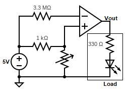
Op-Amp Circuit
To be able to save analog pins, it would be advantagous to be able to digitize our readings from our light sensors by converting the
signal into high and low voltages. We constructed an op-amp comparator circuit that can have its internal resistances adjusted so that we can
choose a threshold voltage that works for our light sensor. Building the circuit took some experimentation, our current design is
shown in the image below.