For this lab, we broke up into the following teams:
1. Alex and Joseph,
2. Ryan and Tyrone,
Alex and Tyrone documented their experience with the prescribed lab exercises, as
both teams were to accomplish the same things.
Collected Materials
Arduino Uno already in box.
We gathered an electret microphone, a microFarad capacitor, a 3 kOhm resistor, some 300 Ohm resistors, a perma protoboard, and several
other various components.
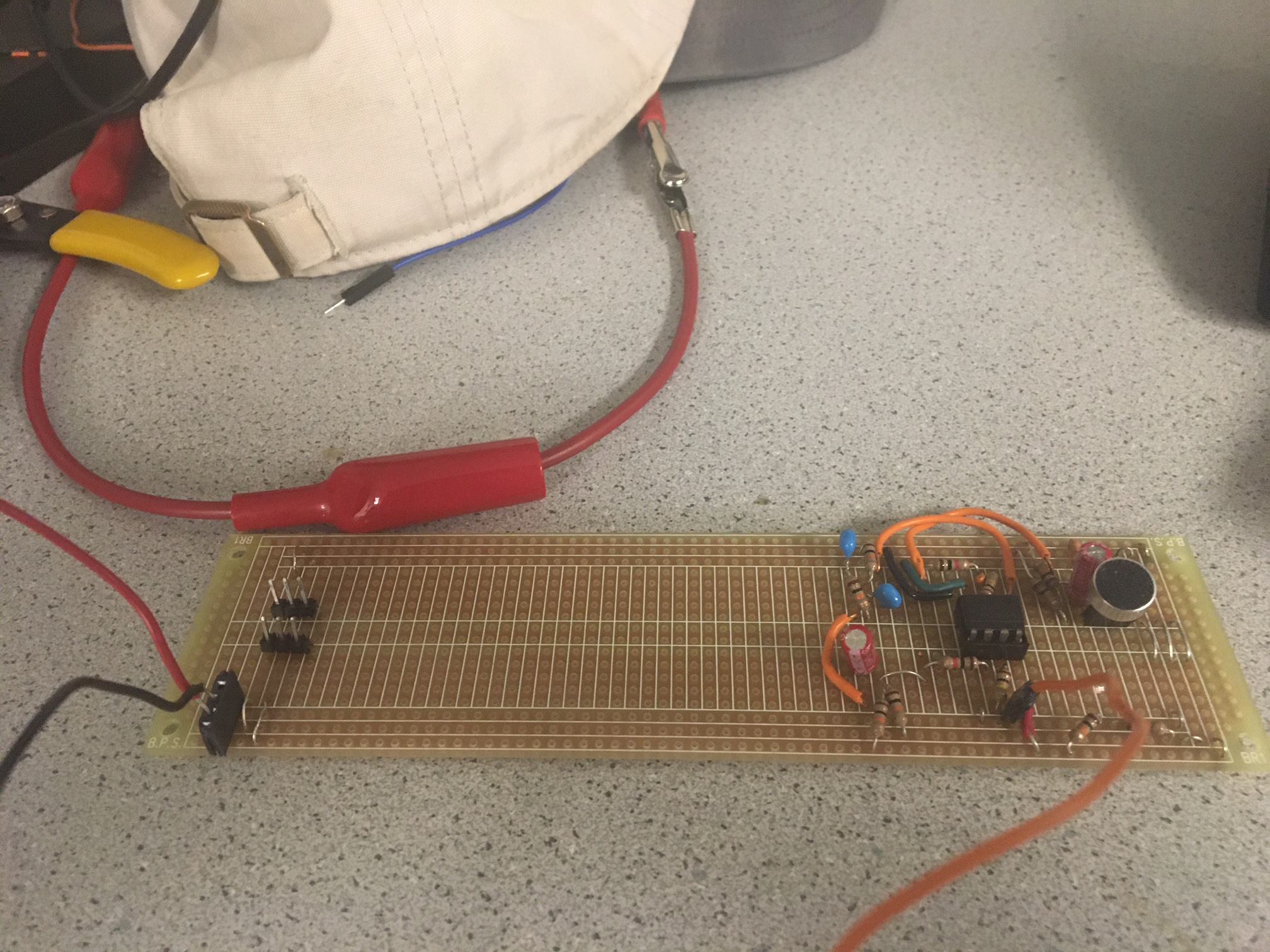
Mic Circuit
Alex worked on the mic circuit. He prototyped the following schematic on a solderless breadboard.
Note that the mic capsule has its own common source amp, and the 3k3 resistor was simply a recommendation.
The first amplifier stage serves as a buffer for filter debugging. The natural mic output
was on the order of 20 mV, and its built-in common source amp is sensitive to the load.
The first amplifier's output runs through a cascade of an RC high pass filter and an RC low pass
filter. The cascade of filters yields a passive band pass filter, with component values
centering the response around 950 Hz. 16 nF capacitors would have been ideal, but were
not available. The second op amp serves to amplify the signal further since we did not
have good results with trying to get closed-loop gain past 100 on the op amps. After
we confirmed that the noted circuit topology worked, Alex soldered the components to a
perma-proto board, adding female pin headers for easy connectivity.
FFT Analysis
A Fast Fourier Transform is essentially an optimized algorithm for computing Discrete Fourier Transforms. It basically takes a signal
over some period of time and converts it into its individual frequency components. This way the user can see which signals are present
and which of those present are the most dominant. The Nyquist Sampling Theorem says the FFT cannot detect frequencies over half the
sampling frequency. Number of samples must be 2n, where n is an integer, however the Arduino Uno does not have enough memory to support
256 samples so n must be less than or equal to 7.
Code
The Arduino's onboard LED was programmed to light up when a frequency of 950 Hz is input into analog pin A0. The peak was expected to
be in Bin 27. This is because analogRead() takes 111.987 microseconds so its sampling frequency fs=1/(111.987e-6)=8929.61 Hz. It is not
necessary to use the board's ADC because 8929.61>950*2=1900>Nyquist Frequency. With a sampling frequency of 8929.61 Hz and 256 samples,
each bin should be about 8929.61/256=35 Hz in size. So 950 Hz should be in Bin 27. While there was a peak in Bin 27, the peak in Bin 19
was larger with more visible changes with changes in frequency. This was measured by outputting the fft of each bin and comparing the
results. Due to this, we used Bin 19 to detect whether or not a 950 Hz sound was being played. When a 950 Hz sound was played, Bin 19
generally output a value greater than 90. Using this data, the built-in LED turns on when Bin 19 has a value of greater than or equal to
90. At this point the message "Sound detected" us also output on the serial monitor. We can now implement this so our robot only begins
functioning once it hears the 950 Hz tone.
We also decided to use an analog mux to deal with some analog pin scarcity. Joseph and Ryan discovered that the mux does not behave
ideally and does have an impedance that influences the reading from sensors. However, we believe this will not be an issue as we can
adjust the threshold values that our arduino looks for to match the additional load. Since we have already done the work tuning the
line sensors, we will leave those in A0-A3 and use A5 as the input from the analog mux. We then have digital pins 0-2 as the select
for the 8:1 switch. Due to how limited our analog pins are in comparison to our digital pins, and how useful analog pins are for
sensors, we believe this circuit will be very beneficial to our robot.