We felt that because of where we were with the lab, we had to split up more than usual.
Alex and Joseph were team robot-basestation-prep. Their job was to think of how the
robot will send the maze to the base station and display it. Joseph also worked on
navigation algorithms, since the next logical step after representing a maze is to
navigate it. Ryan and Tyrone tied up loose ends with lab 2 so that milestone 3 and lab
4 will be well on their way.
What is a maze?
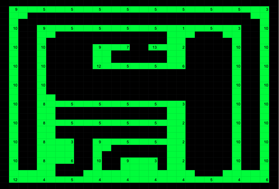
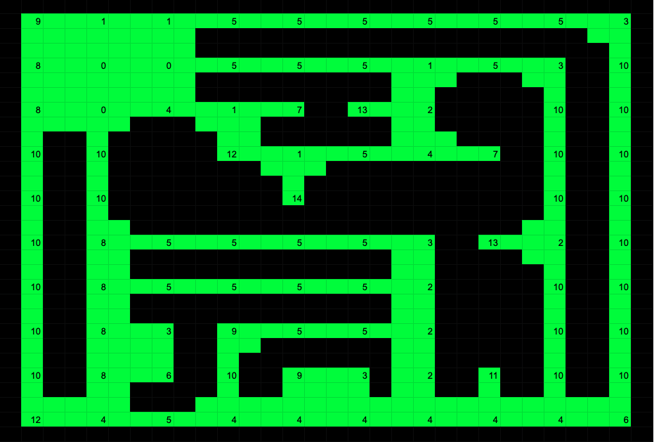
A maze is up to a 10x10 grid of nodes. See two 10x10 mazes below.
Sample Maze 1
Sample Maze 2
What is a node?
Each node has an x-coordinate and a y-coordinate. Each node in the maze
could also have a north wall,
east wall, south wall, or west wall. We can represent this easily in 2 bytes which a shift
register can store. Here is the anatomy of the data portion of our communication packet,
as a Verilog snippet.
(i.e. this is what the switch register holds when the Arduino is done sending stuff)
We decided to allow for 255 nodeTypes so that we could use nodes on-screen to draw stuff
like letters without describing additional hardware.
What is a screen?
A screen, using the ECE 3400 course staff VGA driver, is a 640x480x60Hz array of pixels that
could possibly be drawn in 255 different colors. We currently use four colors, and we also
break the screen down into blocks so that all storage can remain on-chip. (640x480 1-bit
color would require over half of the M9K memory modules).
What is a block?
A block is a 16x16 pixel solid-color block on the screen. The screen is therefore a 40x30
block array. The ECE 3400 staff code originally had the screen set as a 20x15 block array,
but that did not give us enough flexibility. This higher resolution gives us 3x3 block
nodes. That is enough to represent all of the detail about where the walls on a node are.
Shift the X and Y pixel coordinates by 4 to get the block coordinates. The block array
also needs to quadruple in size to 12-bit addressing (from 10 originally).
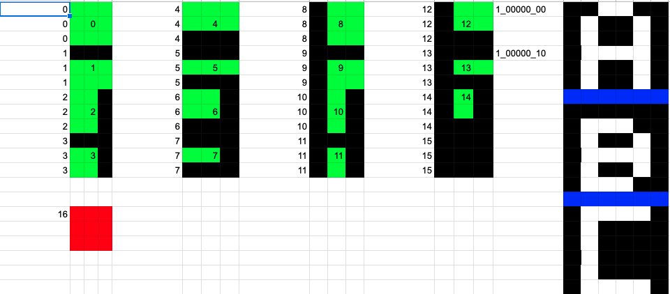
What is a node? (Part 2)
We can revisit what a node is now. A node is also a 3x3 chunk of drawing on the screen.
The Arduino can tell the FPGA in 2 bytes how to update 9 blocks. Here are some of the
nodes that we defined. Note that letters need 4 nodes to draw.
Reader Updater
Now that we know what a maze is, how to draw one, and how to fit one in memory, we need to
know how the FPGA will know what the Arduino wants. The communication scheme is SPI-like.
D_SS rises to begin a packet. The FPGA returns a high D_READY if it is ready. (The Arduino
doesn't actually wait for readiness because that would require extra circuitry to protect
the FPGA). The Arduino then clocks two bytes into a shift register implemented
on the FPGA (using D_CLK and D_IN). D_SS then goes low, signaling that the shift register
should now hold the coordinates and node type of a node to update. The FPGA then denies
any further shift register updates until it finishes updating the node's nine blocks. We
implemented this reading-updating behavior as Moore machine with 6 states. Static lookup
table behavior can reside in LEs or in M9K blocks.
Bit-Banging Arduino
We used a bit-banging solution on the Arduino's end:
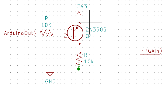
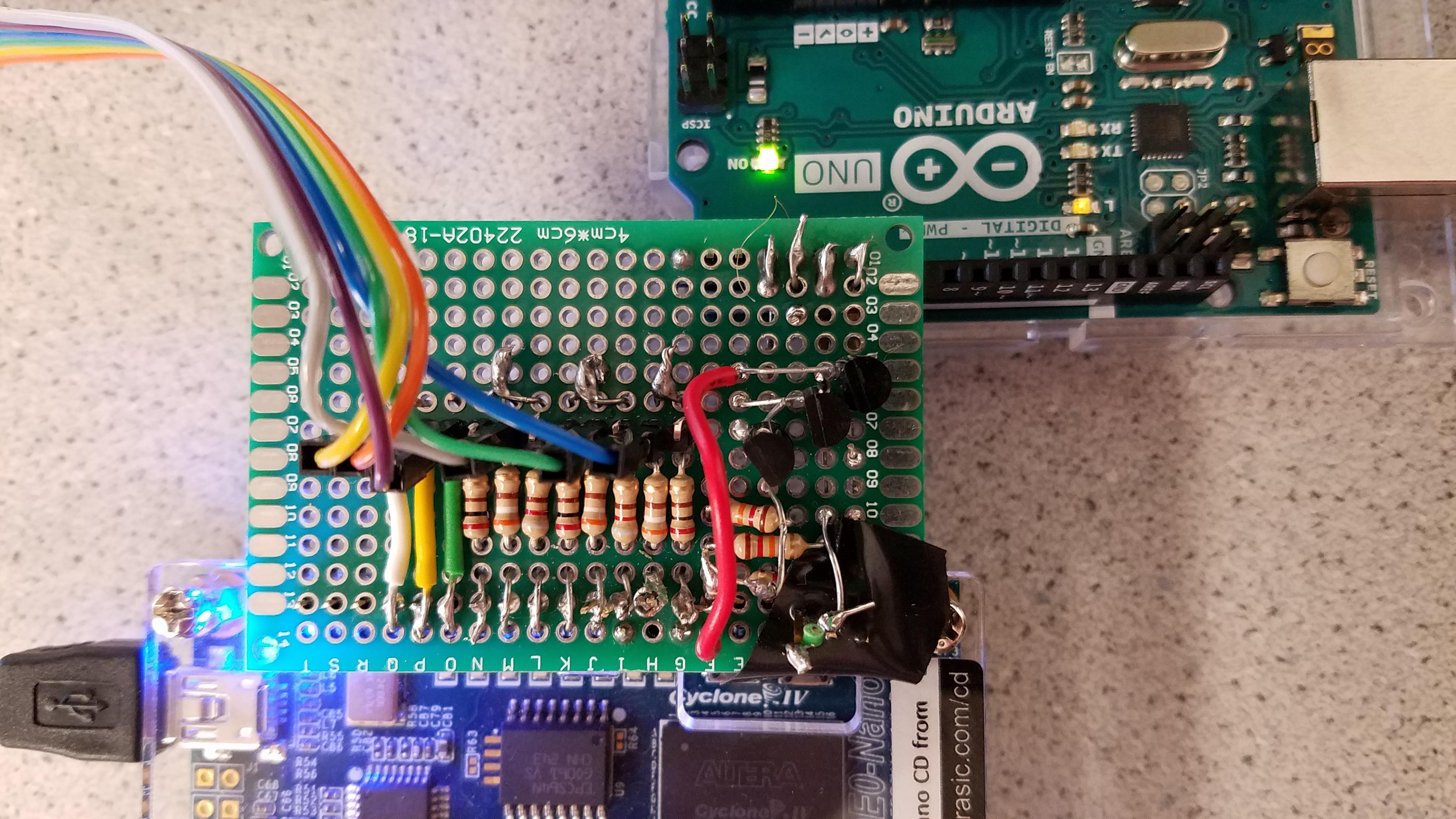
If we didn't lower the Arduino's 5V TTL signals to 3.3V TTL signals, we would fry parts of the
FPGA board. Our solution was to use a transistor and two resistors on each Arduino output
channel. We have to negate the inputs on the FPGA, but that is trivial.
Binary Weighted DAC
To give 8 bit color, resistors of R, 2R, and 4R were connected for the R and G channels,
and just R and 2R for the B channel. R is around 200 ohms to vary signal values between
0 and 1V.
Result
Outside of the lab, Alex soldered a dual hat to join the two devices with the appropriate
circuitry.
The device works, as shown in the video.
We put two example mazes (which change approximately every 12 seconds) onto the
screen along with an example sidebar. The communication is glitchy due to the lack of
shielding. VSync and HSync are moderate frequency signals that have poor shielding, so
they likely sometimes throw off the value of the digital inputs due to electromagnetic
coupling. Better shielding and routing of the
signals would help, but this display is readable enough since the base station Arduino
re-updates the screen as often as it can. Better shielding and routing would likely involve
creating a PCB schematic to be milled, and even then, the problem may actually be something
else. Essentially, the ciruitry works well enough for a handmade prototype and conveys
useful information.