Objective
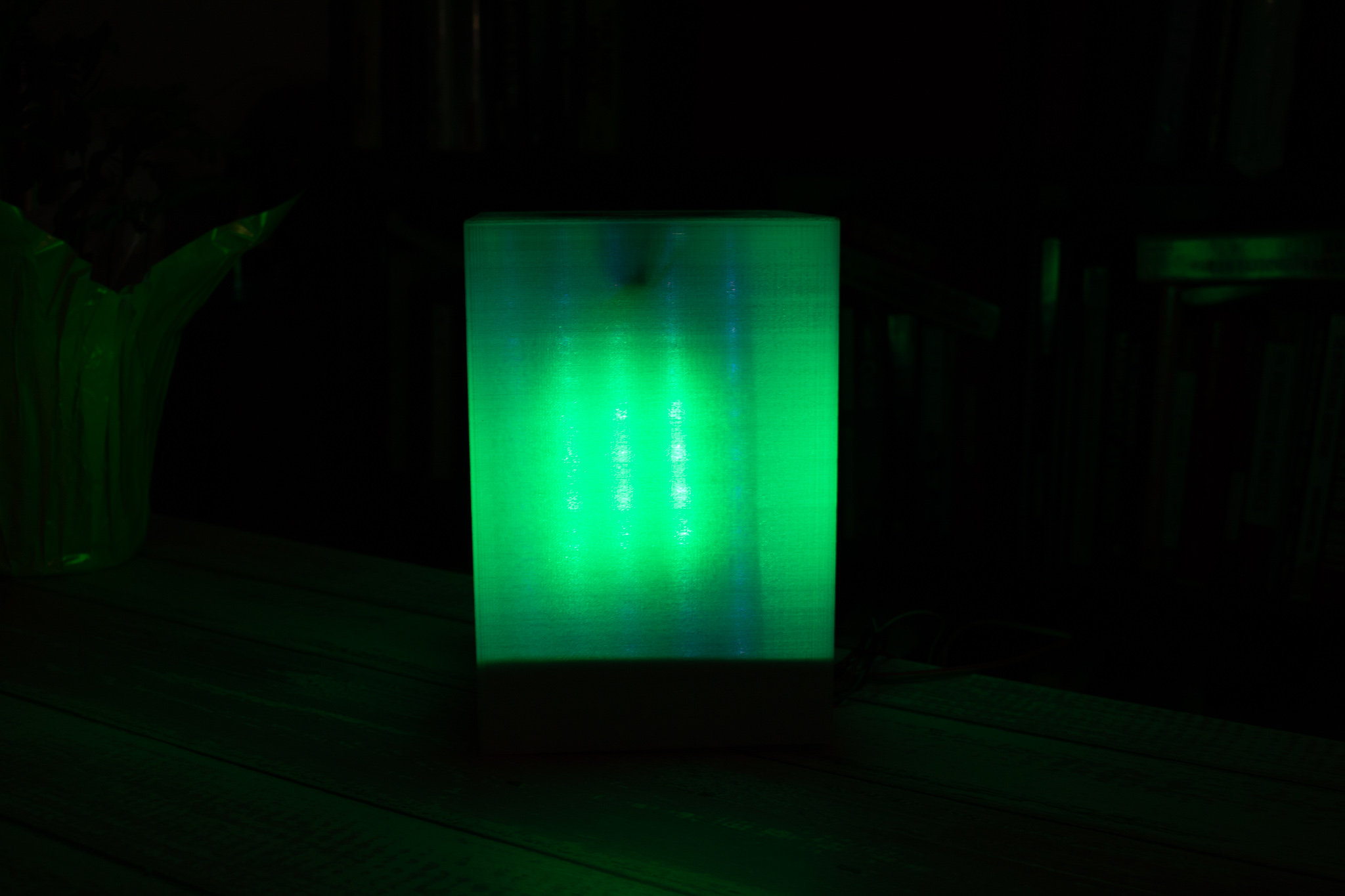
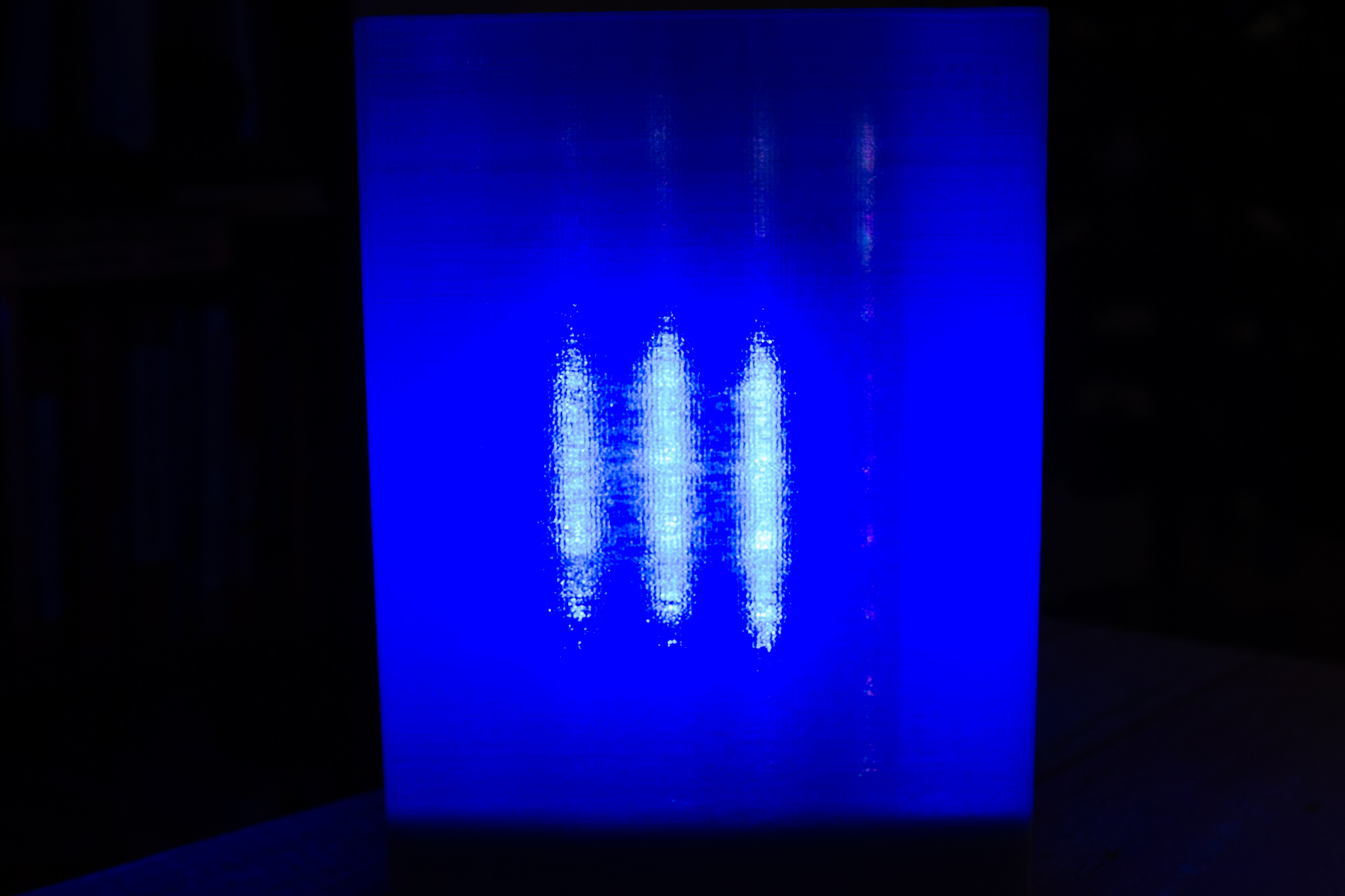
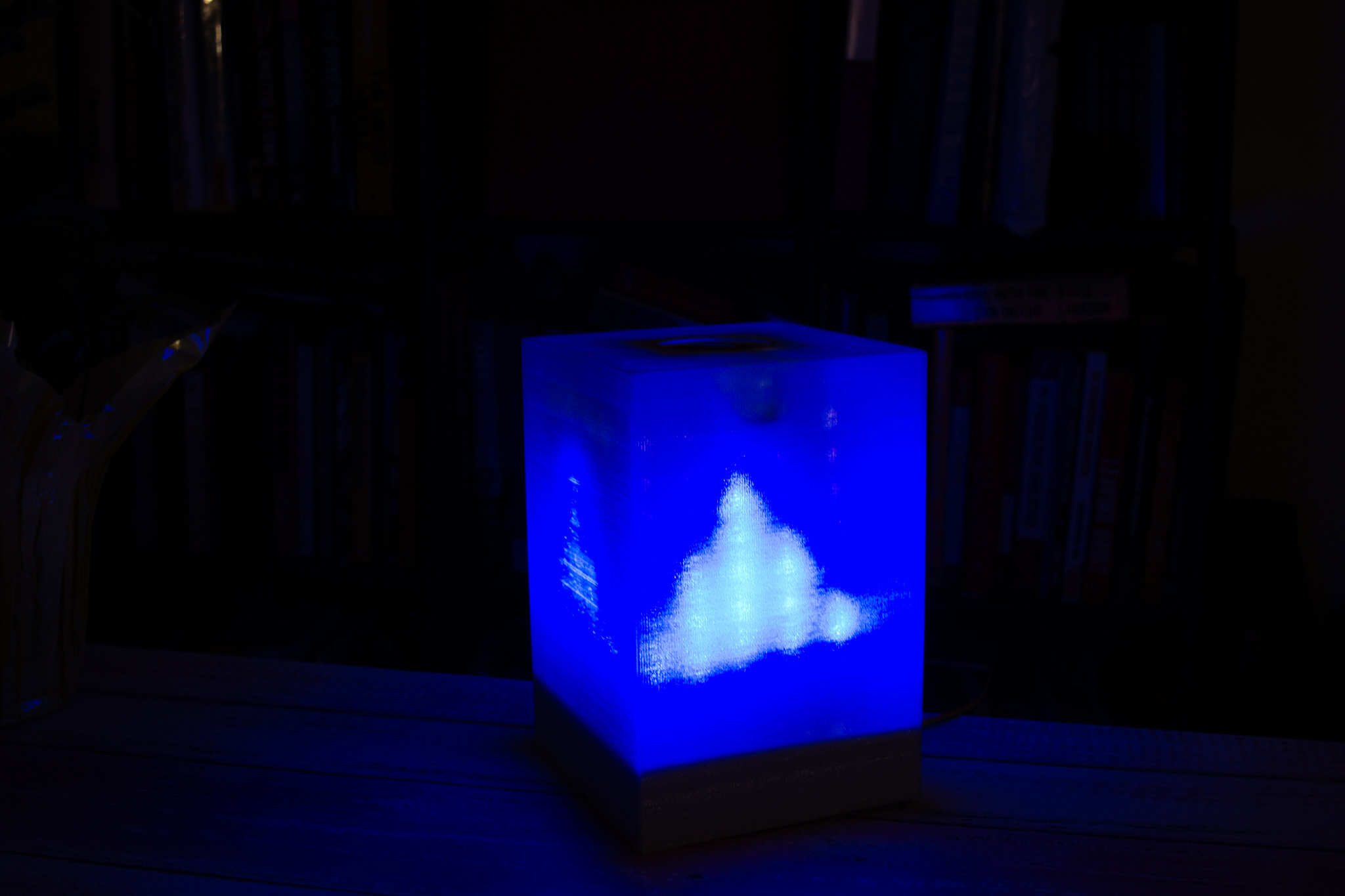
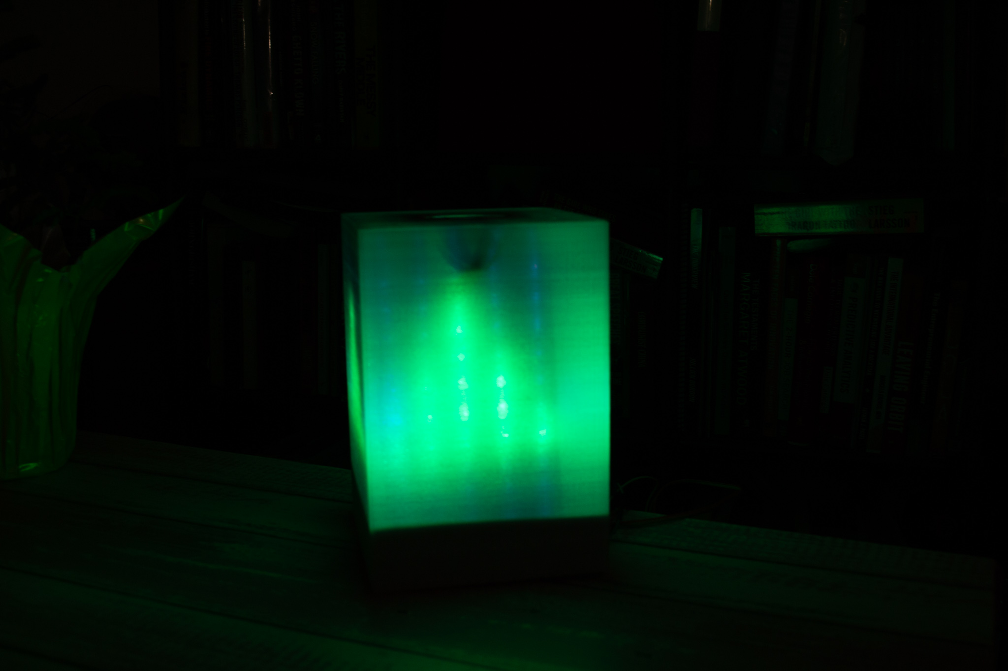
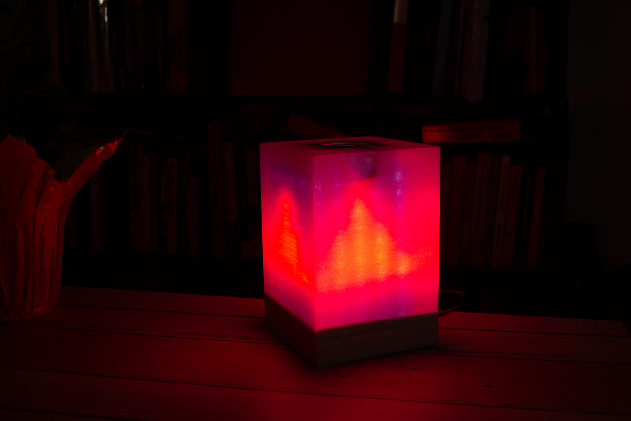
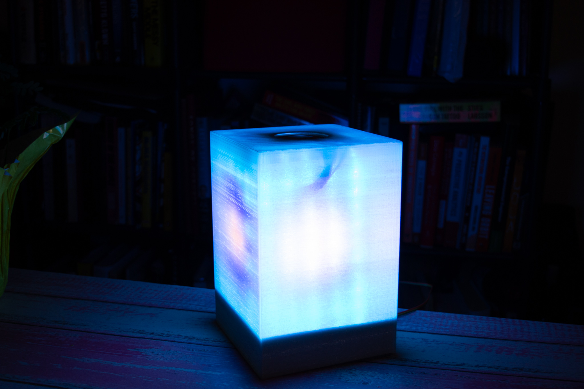
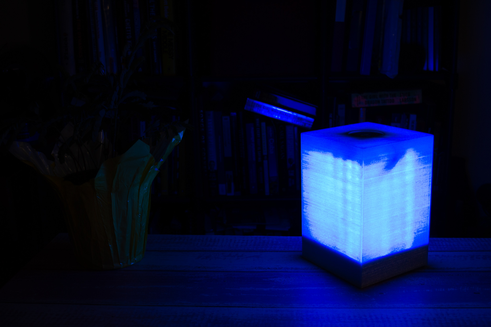
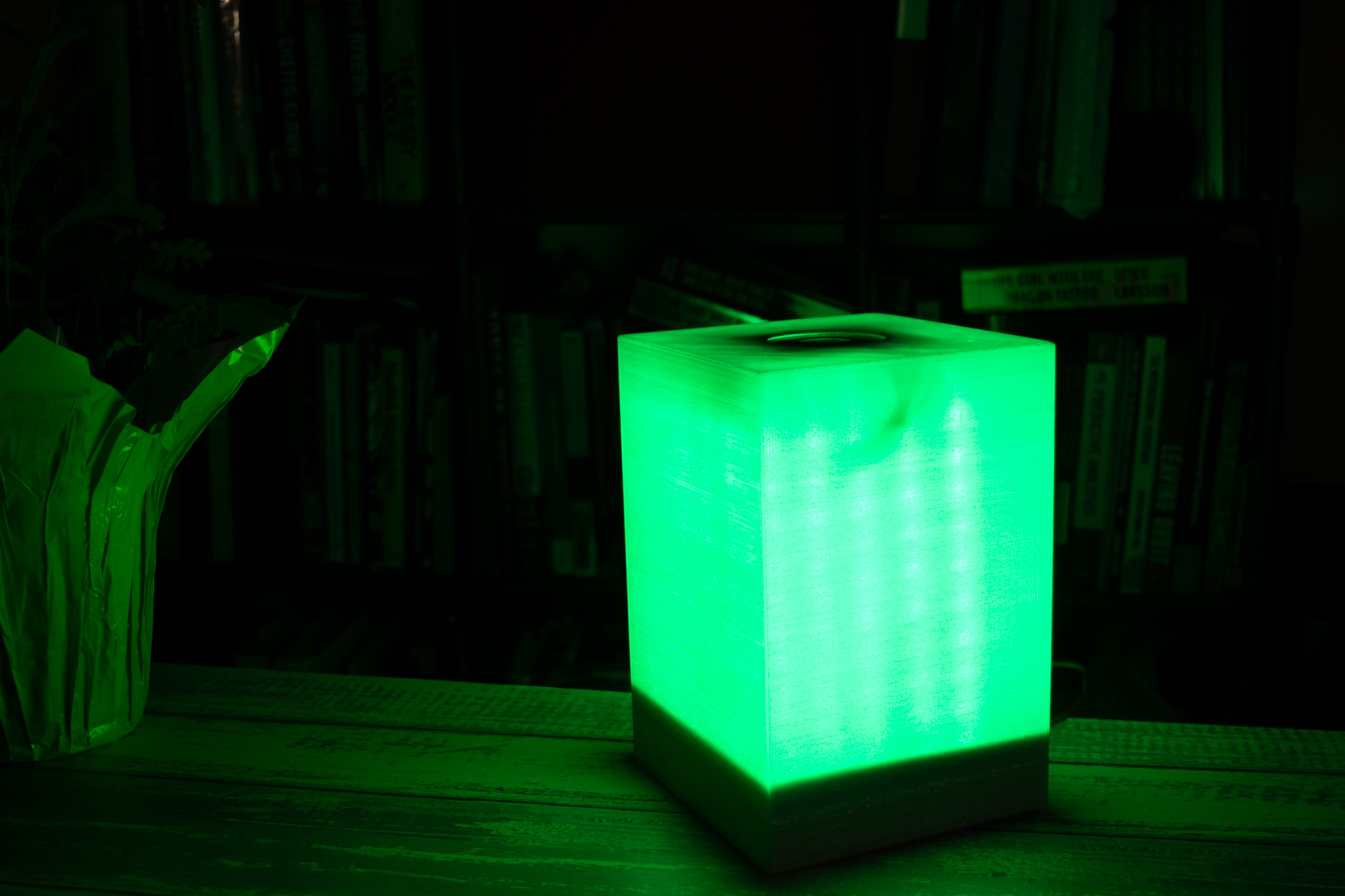
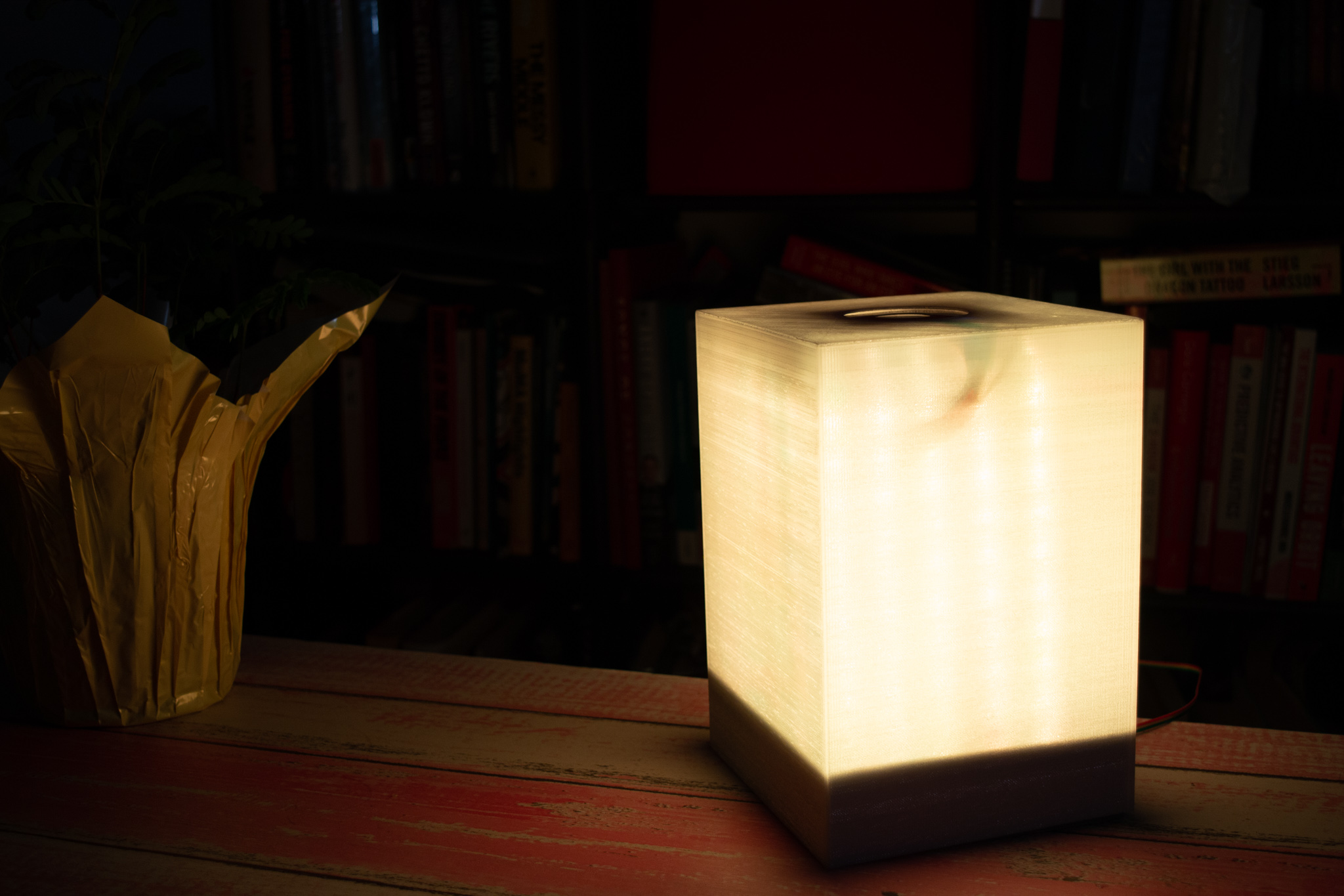
SmartCube is a smart lamp that, paired with a Raspberry Pi, is capable of showing live weather information upon request, such as the temperature and sky condition. Additionally, it provides dynamic animation modes with vibrant colors and computer vision features.
Introduction
The SmartCube was built combining the strengths of the Raspberry Pi and the PIC32. The PIC32 was used to drive all Real-Time intensive tasks. These tasks include reading input from sensors and driving 200 individually addressable RGB LED lights, in addition to a display with the current time and temperature. The Raspberry Pi was used mainly for its user interface design tools, its connectivity capabilities, and its processing power. It runs a multi-layered Graphical User Interface designed with Pygame, which allows the user to see live weather information, communicate commands to PIC32 via Bluetooth Low Energy, and detect shapes and colors to display on the lamp.
The scope of the content of this website limits to the work done on the Raspberry Pi. For more information about design aspects controlled by the PIC32, visit this site.
GUI Design
Our team wanted to design a GUI that resembled a mobile phone app. Considering the features we needed, we decided to design a multi-layered interface with buttons that allow access to the submenus. Upon boot up, the GUI shows a picture of a sun, as seen in the picture below. This picture was chosen because it conveys both the nature of the project (weather), and the turn-on feature. Thus, once the user touches the sun, we access the main GUI, updates the time on the display on top of the lamp and turn on the LEDs.

Main GUI
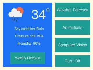
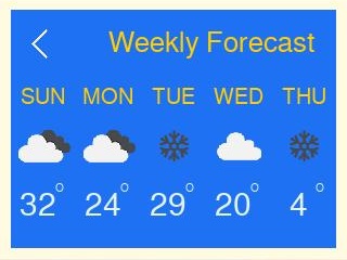
The main GUI is divided into two. As seen in the picture on the bottom left, the left side we placed a division that shows the sky condition, temperature, pressure and humidity, and also includes a “Weather Forecast” button. That button redirects the user to another screen which shows the weather forecast for the upcoming 5 days (seen in the bottom right). Adding more days was deemed unnecessary because it would’ve made the screen look too crowded, and 5 days in advance is still an acceptable forecast time. Once in this screen, the user has a “Back” button to allow the user to return to the main GUI.
Menu Buttons
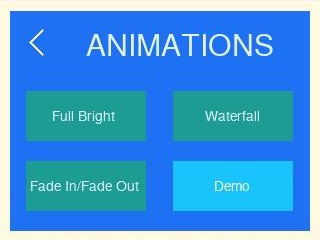
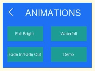
The right side of the main GUI has four buttons: “Weather Mode”, “Animations”, “Computer Vision” and “Turn Off”. Weather Mode displays the animation of the current sky condition on the lamp, in addition to sending the temperature to the display on top of the lamp. Animations takes the user to a submenu, where they can select among four animation modes.
The buttons that control different animations to the lamp change colors when they are pressed, and stay like that until other animation is sent.
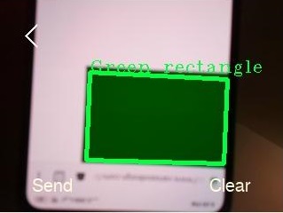
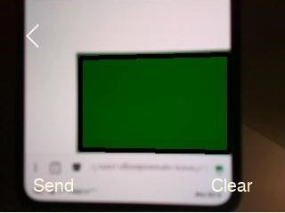
The Computer Vision mode accesses a submenu where the user can see the live camera feed, and detect different shapes and colors. It also includes buttons to Send the information to the lamp once the shape has been correctly detected, and a Clear button to clear wrong detections.
Lastly, the Turn Off button turns off the lamp and returns the GUI to the initial screen (with the sun).
Time/Date
We used the “datetime” library to obtain information about date and time. This information was used in two project features: the weekly weather and the current time. The weekly weather used this library to determine the day of the week of the following 6 days. The weekdays are given as a number by this library, so we had to manually compute the name of the following days by creating a dictionary that maps those numbers to the abbreviated version of the name of the days. In addition, we used this library in conjunction with the function strftime() of the “time” library to obtain the current time, convert it to a readable 12-hr format and cast it to type string, before sending it to the PIC when turning on the lamp.
API Integration
We integrated the OpenWeatherMap API to our code to obtain live weather information. This API offers a free subscription, which offers current weather, weekly forecast, and up to 60 calls per minute, which ensures accurate weather to the second. Each API call returns a string in JSON with lots of information about the current weather, as seen below:
{"coord":{"lon":-76.5,"lat":42.44},"weather":[{"id":804,"main":"Clouds","description":"overcast clouds","icon":"04d"}],"base":"stations","main":{"temp":278.8,"feels_like":275.99,"temp_min":277.04,"temp_max":280.37,"pressure":993,"humidity":100},"visibility":16093,"wind":{"speed":2.6,"deg":70},"clouds":{"all":90},"dt":1576341755,"sys":{"type":1,"id":5041,"country":"US","sunrise":1576326461,"sunset":1576359218},"timezone":-18000,"id":5122432,"name":"Ithaca","cod":200}
This string is parsed using the JSON library to obtain the desired parameters and filter out unnecessary information using the function current_weather(). We parse the temperature, sky condition, icon number to display the appropriate icon, pressure and humidity. The temperature is given in degrees Kelvin, so we wrote the helper function K_to_F() to convert it to degrees Fahrenheit.
Bluetooth
Hardware Used
The Raspberry Pi has a built-in Bluetooth Low Energy (BLE) module, which communicates with HM-10 module (also BLE) connected to the PIC. We used this module because we obtained two paired modules for free from Bruce Land. But BLE communication protocols are different from previous Bluetooth technology, and quality documentation is lacking. Hence, the implementation took hours of trial and error.
The first step was to unpair the modules to use the module built into the Pi. This was achieved by connecting the module to the computer using a USB to TTL cable. Once connected, we used the Arduino IDE serial monitor to communicate with the module and configure it. This could also be achieved with any other serial communication interface, such as Putty. The HM-10 uses AT commands to configure settings and get information from the module. This website contains AT commands and other useful information about the HM-10. To unpair the devices, we used AT+RENEW to reset each module to factory settings. Once unpaired, we obtained their MAC address using AT+ADDR?, to be able to find them and communicate with them.
Software that didn't work
We struggled to find a bluetooth control method that we could integrate into the code. We began trying bluetoothctl, a Linux tool to control the bluetooth interface. We successfully paired the Pi to the HM-10. Since we hadn’t figured out how to receive in the PIC, we kept using Arduino IDE serial monitor to test communication . The monitor was set up to receive information at a baud rate of 9600, and set to “No line ending”, because these were the default settings on the firmware version of the HM-10 module we had. We successfully sent messages from the Pi to the HM-10 and were able to see them in the serial monitor. However, we couldn’t find a way to integrate this tool into the code. We found the same hurdle when trying hcitool and gatttool. They were capable of integrating to the code, but it involved too much complexity, because there are no direct commands that “send” the information. Rather, they all open a separate interface with a separate set of commands. This layering proved challenging when trying to send information while running the GUI.
Software that worked
Luckily, we found bluepy, a Python library that facilitates Bluetooth communication. With bluepy, we could open communication with the HM-10 module while running the GUI code, and respond with very little latency to button presses that sent commands to the PIC. We used the functions Peripheral.connect() to connect to the module, passing it the previously obtained MAC address, Peripheral.writeCharacteristic() to send the data to the HM-10 module, and Peripheral.disconnect() to disconnect the module once the program finished running. The disconnect function must be called before calling the connect function again, or else it will cause an error. We recommend the communication line is opened and remains so until the program finishes to avoid errors. The function Peripheral.writeCharacteristic() took in the write handle and the string to be sent as arguments. After hours of researching, we found on this Raspberry Pi Stack Exchange forum that we needed to write to handle 0x0012 of the HM-10 module, which corresponded to the characteristic 0000ffe1-0000-1000-8000-00805f9b34fb. This characteristic is used by default by the HM-10 to read/write up to 20 bytes at a time.
Message Encoding
Due to this size restriction, we decided to limit the number of characters we were sending at once, to make it easier to decode on the PIC side. We first tried sending strings followed by the carriage return sequence character “/r”, but the PIC was inconsistent to receive these messages. The PIC seemed to behave very well when using a termination count instead. This way, the PIC processed the data buffer when it had received the specified number of characters. We first limited it to only one, but when sending the current time to display it on the lamp, we found it easier to increase the string size. In the final iteration of our software, we decided to limit the character count to 5.
The hour was sent with the format “thhmm”, where “t” indicated that the received string corresponded to the time, and the other four characters corresponded to the actual time. For instance, “t1045” corresponded to 10:45. Since the clock has a 12-hrs format, there is no distinction between am and pm. The rest of the commands were also written as 5-character strings, but on the PIC side we only processed the first letter to decode which command we wanted to execute. The other 4 characters were filled to maintain the string length of 5 characters that worked so well with the PIC.
Observations
When testing, we found that the BLE module on the Pi is capable of connecting to more than one BLE module at a time. We also observed that sometimes when restarting our program after it closed, the Pi wouldn’t connect to the HM-10. This error seemed to clear when the HM-10 was power cycled. Also, when running the Pi from the power bank, it would sometimes have problems to connect to the HM-10. This seemed to be related to the battery level, since it worked perfectly when the battery was freshly charged, and when we switched to the DC adapter as power supply.
Computer Vision
Hardware
We obtained a piCam V2 from professor Skovira. This camera connects to our board via a dedicated camera port. It's supports static images 3280 x 2464 pixel, and also 1080p video at 30fps, 720p at 60, and 480p at 90. However, our goal was to display the live feed of the video into the piTFT while integrating the feature to the GUI experience seamlessly. To that end, we had to convert each frame down to 320x240 pixels, and yield control of the frame rate to pygame, which displays it in the piTFT. However, for other applications, it might be better to drive the display directly with the “cv2” library, because it looks smoother and faster.
OpenCV
We installed the OpenCV library using the guidelines posted in the website resources. Installation was completed with no issues. However, when trying to use the library following the examples in the Pi Camera and OpenCV guidelines by Xitang Zhao, we found some errors.
Errors using the library
Xitang’s example code for OpenCV didn’t work. The camera would connect, but when executing videoCap.get(cv2.cv.CV_CAP_PROP_FRAME_WIDTH), it returned an attribute error saying that the module object didn’t have an attribute ‘cv’. Many forums said that the problem could be circumvented by deleting the ‘.cv’ following the “cv2” in the function call, but that yielded the same attribute error, this time with CV_CAP_PROP_FRAME_WIDTH. With some research, we found that pip-installing “opencv-contrib-python” could solve the problem, but another error surfaced saying “No matching distribution was found for opencv-contrib-python”. Moving on, we decided to use a different example code from this page in the OpenCV Tutorials page, which successfully connected to the camera and displayed the video feed.
Then, we proceeded to process the image. We first attempted to use template matching, but we couldn’t, because it required “matplotlib”. When installing this library, we got a MemoryError. The error turned out to be caused by a faulty caching mechanism pip uses, which needs patching. We solved this problem by uninstalling “matplotlib”, and reinstalling it again using sudo pip --no-cache-dir install matplotlib, as advised in this website. After successfully installing “matplotlib”, we tried using it, but it wouldn’t import correctly because it couldn’t find a module named functools_lru_cache in a package named backport. Some research yielded that this module was missing on some versions of the library, so we tried reverting back to older versions, until we installed version 2.0.2 with pip install matplotlib==2.0.2.
Finally, we tried to run the example code for template matching given in the Tutorials page of OpenCV, but we got the error “couldn’t find foreign struct converter for ‘cairo context’”. This problem was solved by installing the package “python-gi-cairo” using sudo apt-get install python-gi-cairo, as instructed here.
Choosing the right algorithm
We initially tried to pursue individual face recognition to load/store personalized settings in the lamp, but due to the difficulty and lack of time for this implementation, we decided to pursue something more feasible. That’s why we set on shape/color detection. We first tried using template matching to achieve this. Template matching consists in finding an image (or template) within a larger frame. It works by overlaying that template over every possible space within the frame and calculating how much overlap there is. The algorithm then returns the zone with maximum overlap. The example code given in the Tutorials page of OpenCV illustrates this by finding a cutout image of a face within a full-body picture. This method proved effective for static images, but we couldn’t get it to work properly for real-time shape detection. Thus, we moved on to implement contour detection with color masking.
Detecting shapes and colors
We followed the tutorial here to learn how to implement the detection of shapes by counting the number of contours. But this tutorial only covered detection of red rectangles. We expanded it to detect 2 shapes and 3 different colors.
Contour detection and color masking work together in our algorithm, because we need to isolate colors effectively before detecting the shapes in those colors. To do this, we convert the color format into HSV, and calibrate the thresholds for detection before we actually run the code. This calibration is performed as explained in the pysource.com tutorial linked above. We recommend performing the calibration in lighting conditions dimmer than the environment where it will be used, so that it will be capable of detecting and masking out colors more effectively.
Once each color (red, blue and green) were being correctly masked out, we proceeded to use contour detection to detect both triangles and rectangles. Before proceeding to count the contours and determining the shape accordingly, we use the function approxPolyDP() to eliminate the noise in the detected edges, and approximated them to lines. This reduced misreads and false detections drastically. But we were still having some false detections, especially with triangles. Sometimes the algorithm mistakenly displayed them as rectangles, because some temporary movement or shade in the image would cause a 4th side to be detected. This was mitigated by adding some debouncing to the reads.
We set thresholds for the detection of both shapes. The camera would have to detect the shape for several consecutive cycles before asserting whether it was a triangle or a rectangle. Triangles were often confused as rectangles, but never the other way around, so the threshold of the triangles was set 10 times smaller. This improved the accuracy of the detection to over 95%. It could’ve been even more accurate, but it would’ve been much slower and irritating. Instead of paying in detection latency, we included on-image text that gave instant feedback of the shape detected, as seen in the picture below. showed the name of the shape when it was detected. We implemented a “Clear” button on the Computer Vision screen to discard false detections, and avoid sending them to the lamp.
The program flow can be observed in the video of the results below.
Results
Conclusions
This project fulfilled almost every goal that we set out to achieve: it was capable of connecting to the internet, downloading live weather information, integrating this information seamlessly with a GUI, communicating commands via BLE to an HM-10 module connected to a PIC32, and detecting shapes and colors using OpenCV. We created a fully functional consumer product, with a polished finished look and attractive features.
Some aspects of the project were very challenging, especially the Bluetooth communication. The challenge with Bluetooth consists mainly on lack of good documentation about how to set up two-way communication with BLE devices, such as the HM-10 module we used. Thankfully, everything we set out to do only required one-way communication from the Pi to the PIC, but in wireless communication it is usually recommended to have the ability of communicating both ways.
Future Work
Time, as always, was a limiting factor in this project. If given more time, we would have explored two features: face recognition and voice commands recognition. At first, we wanted to include face recognition to allow the lamp to store/load personalized settings based on the person who is using the lamp. The other feature, voice recognition, would have been a fantastic complement to the lamp, since we would have been able to interact with the lamp without manually interacting with our Pi assembly. This proves useful in many situations, as evidenced by the large existing market for smart home assistants such as Google Home and Amazon’s Alexa.
Budget
As seen above, the total price of the parts we used was $99.95, but all the parts were provided by the instructor, so there was no cost out of pocket.
References
BassBot website https://opencv-python-tutroals.readthedocs.io/en/latest/py_tutorials/py_gui/py_video_display/py_video_display.html https://stackoverflow.com/questions/29466663/memory-error-while-using-pip-install-matplotlibhttps://stackoverflow.com/questions/42279510/couldnt-find-foreign-struct-converter-for-cairo-context
http://www.martyncurrey.com/hm-10-bluetooth-4ble-modules/#getStarted
ECE 5725 Lectures
ECE 5725 References for Pygame, OpenCV and BLE
Team and Work Distribution
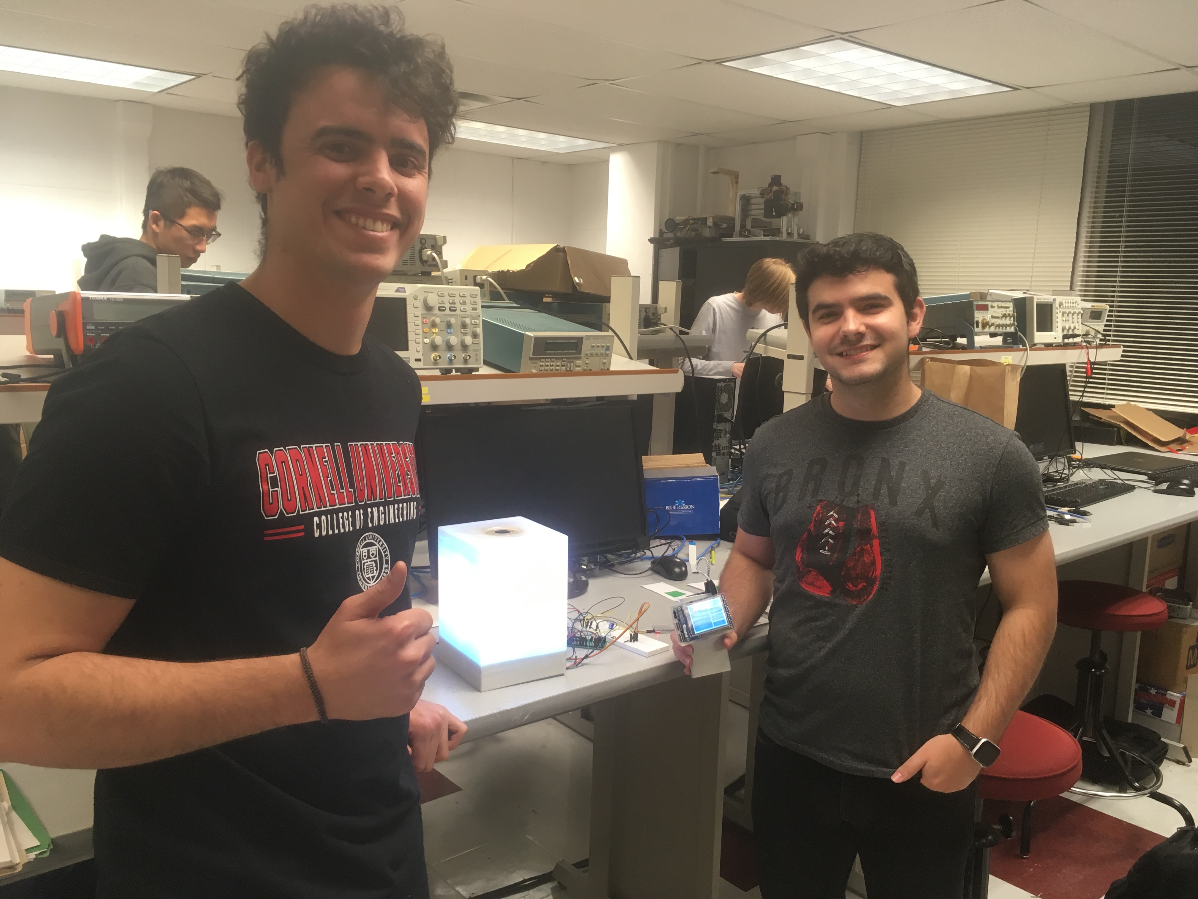
Our team is composed by Juan Joel Albrecht (right) and Alberto Lopez Delgado (left).
Juan Joel (ja643) is completing his M.Eng. in ECE. He enjoys embedded systems and playing soccer. For this project, he coded the GUI and performed the API integration.
Alberto (al2367) is on his Senior year at ECE. In his free time he plays Fifa and watches anime. For this project, he coded the computer vision and bluetooth features.
- All
- GUI
- Lamp
Blue Square
Blue triangle
Green Square
Green Triangle
Red Square
Red Triangle
Clear
Clouds
Rain
Snow
Blue
Green
Pink
Red
Yellow
Animations
Shape detected
Detecting shape
Main Screen
Highlighted Button
Turn-on screen