LAB 3: Filtering and FFT
Objectives
Materials
- Robot
- Capacitors and resistors
- Jump wires
- 1 x 9V battery snap connector
- 1 x LM358 op-amp
- Speakers
- Pushbutton and resistor
Procedure
Microphone Circuit and Signal Processing using MATLAB
The parts needed for the circuit were gathered. A piece of wire was soldered at the end of each lead of the microphone.
Microphone Circuit without Amplification
One the robot's main board the circuit was implemented using the Schematic below.

Once completed, the ADC on the Nano board was setup to Free running mode. Then, the the microphone was connected to an analog pin. Using MATLAB, sound of increasing frequencies (500 - 500.1 Hz) was played over the speakers for a duration of 2 seconds. The serial monitor was opened and the ADC conversion performed by the Nano was fetched using our MATLAB code. Lastly, a Fourier analysis was performed on the data in MATLAB. Upon the Fourier analysis, peaks at the playing frequency 500 Hz and at its harmonics were observed on the plot as shown below.

Amplified Microphone Circuit
The amplified circuit was build using the schematic below.

The previous steps mentioned aboved were used to fetched and the Fourier analysis was performed using MATLAB. This resulted in a larger peak near 500 Hz.

Microphone Circuit and Signal Processing using FFT on Arduino
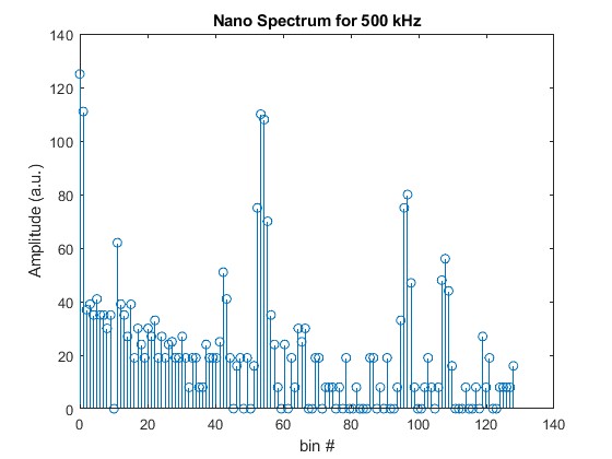
In this section, the Arduino FFT library was used for processing the data. The ADC was kept in free-running mode. Using interrupts on TCA, the 257 ADC values were collected approximately every 1/2 ms. This time, MATLAB was used to play sound over the speakers for 2 seconds. The Fourier analysis was then performed by the Nano and the spectrum was displayed over the Serial Monitor. The data was then visualize using MATLAB. The implementation mentioned above were further tested for frequencies 700 Hz and 900 Hz. It is worth mentioning that an override button was added on the robot's breadboard. More Testing is still needed to confirm that the button can be used for navigation.
FFT Arduino Spectrum Visualization


Robot with Amplified Microphone
