dag334.github.io
Showcasing projects created in ECE 3400 (Intelligent Physical Systems)
Lab 2: Phototransistors & Display
In this lab, we developed the treasure detection aspect of our robot. We installed three phototransistors to detect the presence of the infrared (IR) LED, which will be attached to the treasure, and a 7-segment display circuit, which will serve as our base station to which the robot will relay the frequency of the treasure’s IR LED.
Part One: Phototransistors
The goal of part one is to install a phototransistor such that the voltage fed into the Arduino’s analog pin is proportional to the IR light detected. When the analog voltage rises above our predetermined threshold of 1.2V, the frequency at which the LED blinks is printed to the serial monitor.
Materials:
- Robot Constructed in Lab 1
- One Long Breadboard
- One Infrared (IR) LED w/ Current-Limiting Resistor
- Three LTR-301 Phototransistors
- Three 2kΩ Resistors
- Signal Generator
- Oscilloscope
The phototransistor circuit consists of three phototransistors and three 2kΩ resistors laid out as pictured below:
Fig. 1: Circuit diagram of a single phototransistor
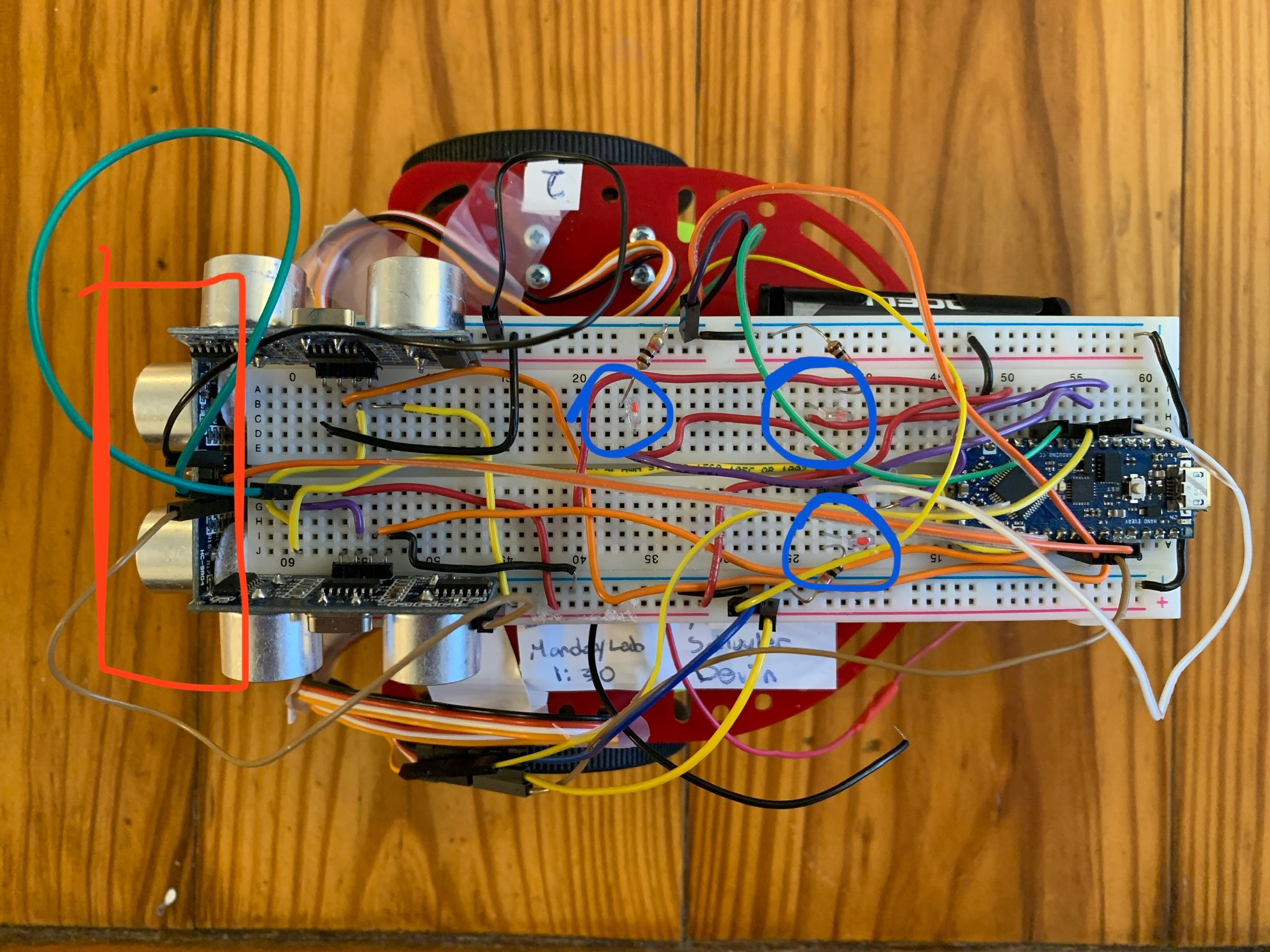
Fig. 2: Phototransistors on robot (circled in blue), each in a different orientation with respect to the front of the robot (boxed in red)
To test our phototransistors, we applied a 1.2V peak-to-peak square wave to an IR LED at 9 kHz. The voltage across each phototransistor produced the image below:
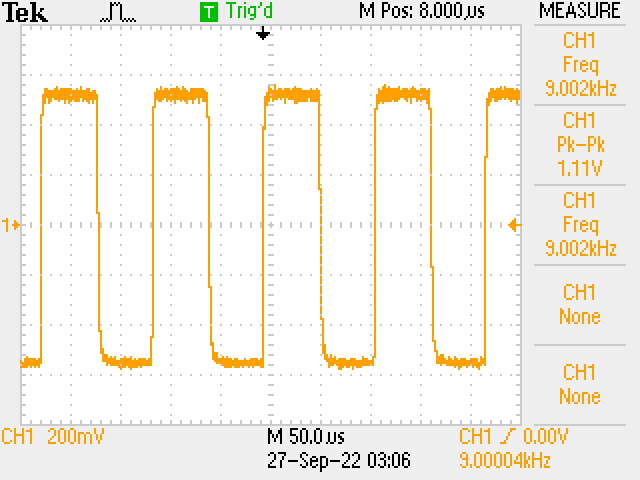
Fig. 3: Phototransistors output from 9kHz IR signal
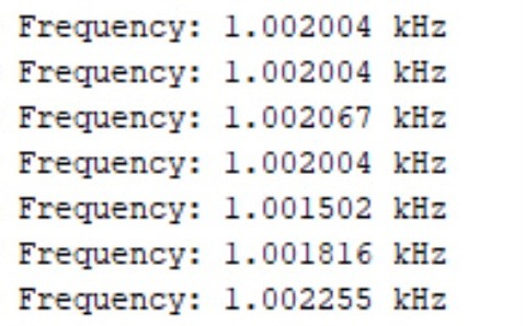
Fig. 4: Serial monitor printout from phototransistor
Part Two: 7-Segment Display
The goal for part 2 is to light each of the segments on each of the 4 digits and successfully display the number 2468.
Materials:
- Separate Arduino Nano Every
- One Breadboard
- One TDCG1050M 4-digit 7-Segment Display
- One SN74HC595N Shift Register
- Four PNP 2N3906 Transistors
- Four 4.6kΩ Resistors
- Eight 330Ω Resistors
We built the 7-segment display circuit on a separate breadboard according to the schematic pictured below.
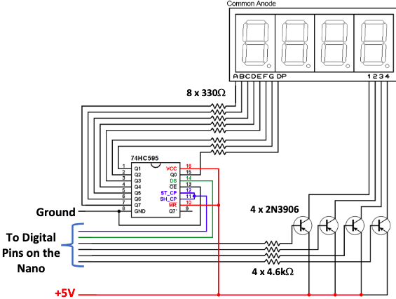
Fig. 5: Schematic for connectivity between shift register, 4‐digit 7‐segment display, transistors, resistors, and Nano
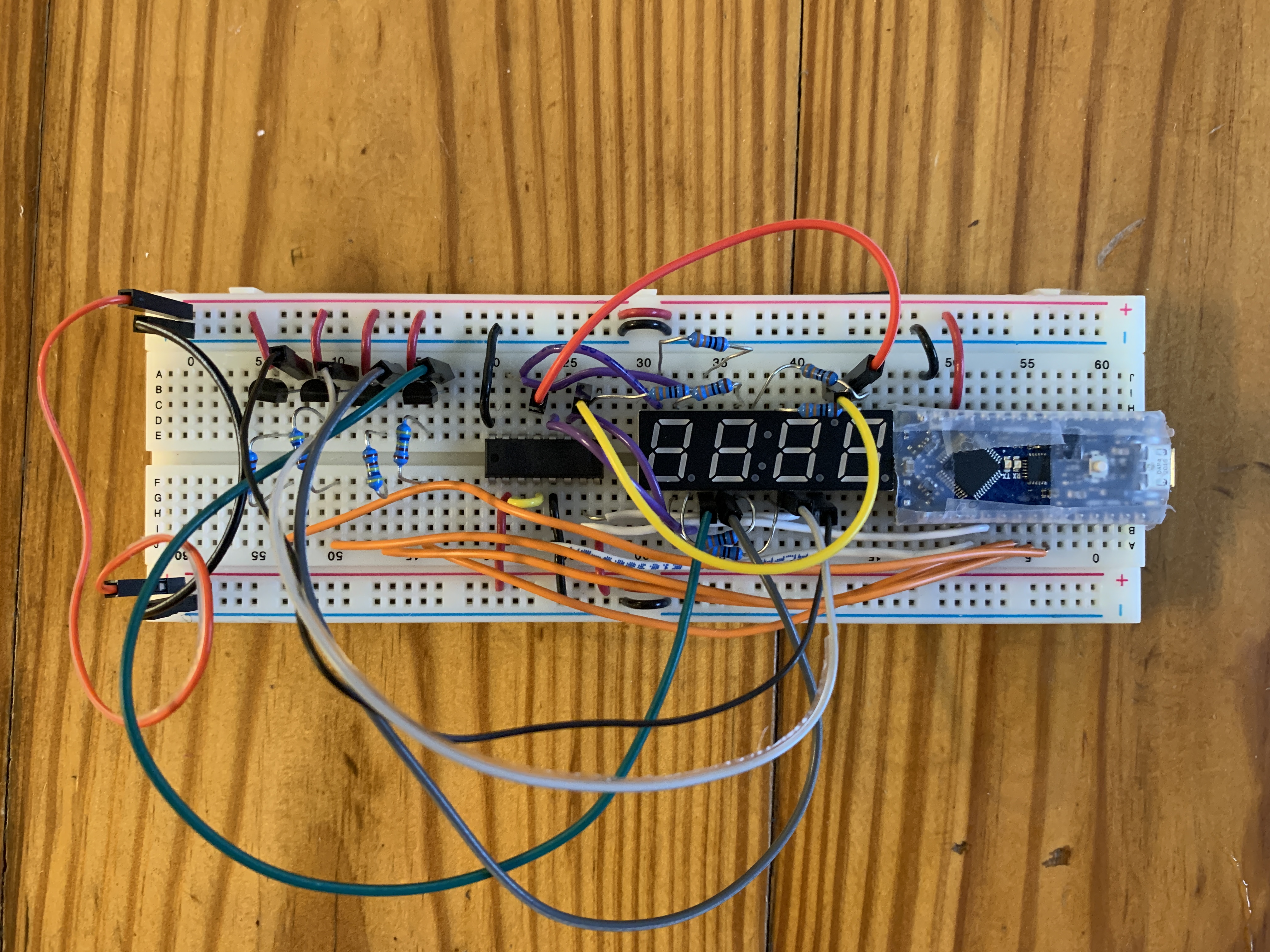
Fig. 6: Completed 7-segment display circuit
After verifying functionality of all segments, we displayed our test number to conclude Lab 2.
Fig. 7: Displaying test number '2468'