dag334.github.io
Showcasing projects created in ECE 3400 (Intelligent Physical Systems)
Lab 3: Filtering and FFT
In this lab, we implemented sound detection and filtering on our robot that will begin the navigation process once the desired frequency is detected.
We installed a microphone with an amplifier to pick up the audio signal and configured it to collect data and perform a Fast Fourier Transform (FFT) to create a frequency spectrum stem plot. The completed robot is equipped with a microphone override that signals the robot to begin navigation without the audio cue.
Simulation of Full Microphone Circuit
Before using any hardware, we characterized the circuit’s behavior using a simulation created in LTSpice. The amplifier circuit consists of three smaller circuits connected as one.
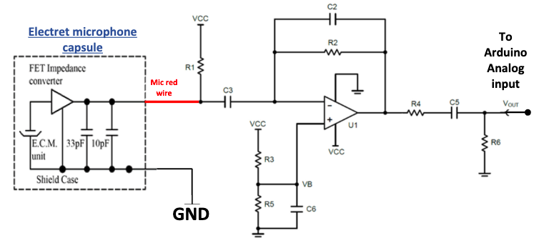
Fig. 1: Full microphone circuit schematic
Materials:
- Robot Constructed in Labs 1 & 2
- One LM358 Op Amp
- Three 100kΩ Resistors
- One 75kΩ Resistor
- One 4kΩ Resistor
- One 50Ω Resistor
- Two 2.2µF Capacitors
- One 0.22µF Capacitor
- One 100pF Capacitor
- Laptop/Computer with Speakers
Circuit 1: Bias Resistor & Coupling capacitor
Output from the microphone is fed directly into the bias resistor and coupling capacitor. The resistor biases the JFET microphone by 5V, which is above the typical microphone operating voltage of 3V. The capacitor acts as a high pass filter with a cutoff frequency around 180 Hz. The output from this circuit is fed into the negative terminal of the op amp.
Circuit 2: Op Amp Biasing Circuit
Two of the 100kΩ resistors act as a voltage divider to bias the op amp at half the power source voltage of 5V. The 2.2µF capacitor filters out Johnson-Nyquist noise and acts as a low pass filter along with the two resistors with a cutoff frequency around 1.44 Hz. The output from the high side of the capacitor is fed into the positive terminal of the op amp.
Circuit 3: Active Low Pass Filter
Using the input from the last two circuits and a negative feedback branch consisting of a 75kΩ resistor and 100pF capacitor in parallel, the LM358 op amp behaves as an inverting amplifier. 5V is applied to the op amp with the low terminal connected to ground.
Circuit 4: AC Coupling Network
The output of the circuit thus far is fed into the final three components, which make up the AC coupling network. A 50Ω resistor limits the current into a 2.2µF capacitor, both connected in parallel. The capacitor acts as a high pass filter, and a 100kΩ resistor provides the capacitor with a discharge route to protect the components of the Arduino.
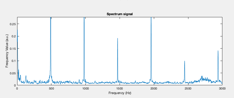
Fig. 2: Output signal of the full amplified microphone circuit responding to a two second 500Hz sound wave
After successfully reading from the microphone, we configured the Arduino to create a 256-bin array of frequency values ranging from 500Hz to 900Hz with which we created frequency spectrums to display in MatLab.
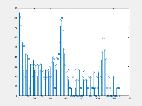
Fig. 3: Amplitude of a 500Hz Sound Wave vs. bin number
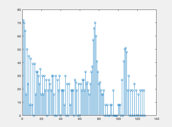
Fig. 4: Amplitude of a 700Hz Sound Wave vs. bin number
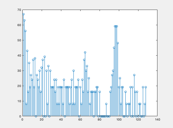
Fig. 5: Amplitude of a 900Hz Sound Wave vs. bin number