ECE 3140 | CS 3420 Final Project
Aryaa Pai (avp34) | Krithik Ranjan (kr397)
Introduction
In this project we tried to create a fun, easy game to play with our friends across the world while staying at home in these times of crisis. Our game, called CroK64, is a 2-player, simple, indoor version of the popular backyard game, Croquet, where players hit balls with a mallet through a series of wickets or hoops. In our game, both the players use the FRDM-K64F as the gaming device (the mallet), which they physically move around in order to hit the balls in different directions, trying to get their ball through all the wickets before their opponent. The boards are connected to players’ computers using the USB cable, which then connect over the internet to communicate the state of the game with the other player. The detailed gameplay is described in the next section.
System Overview
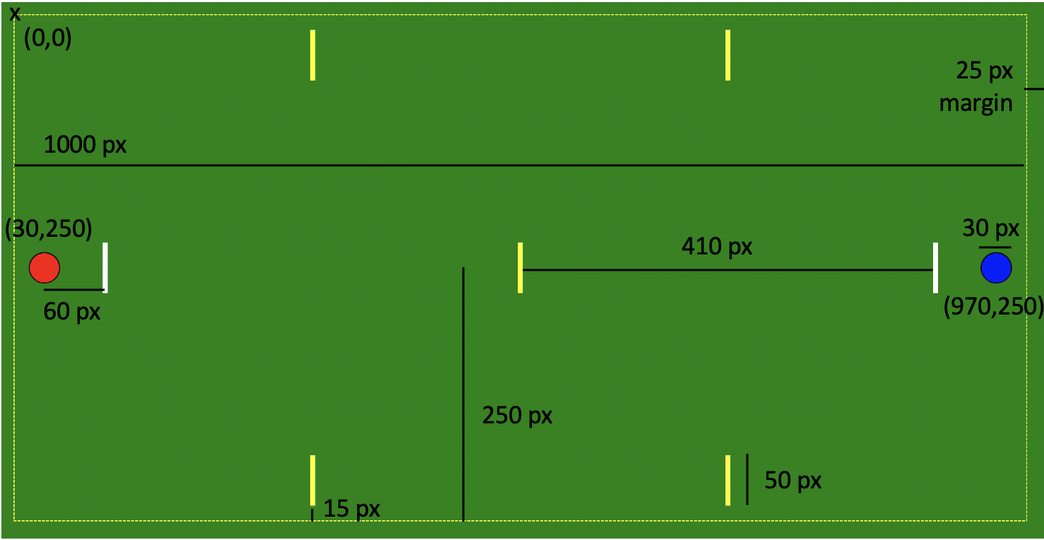
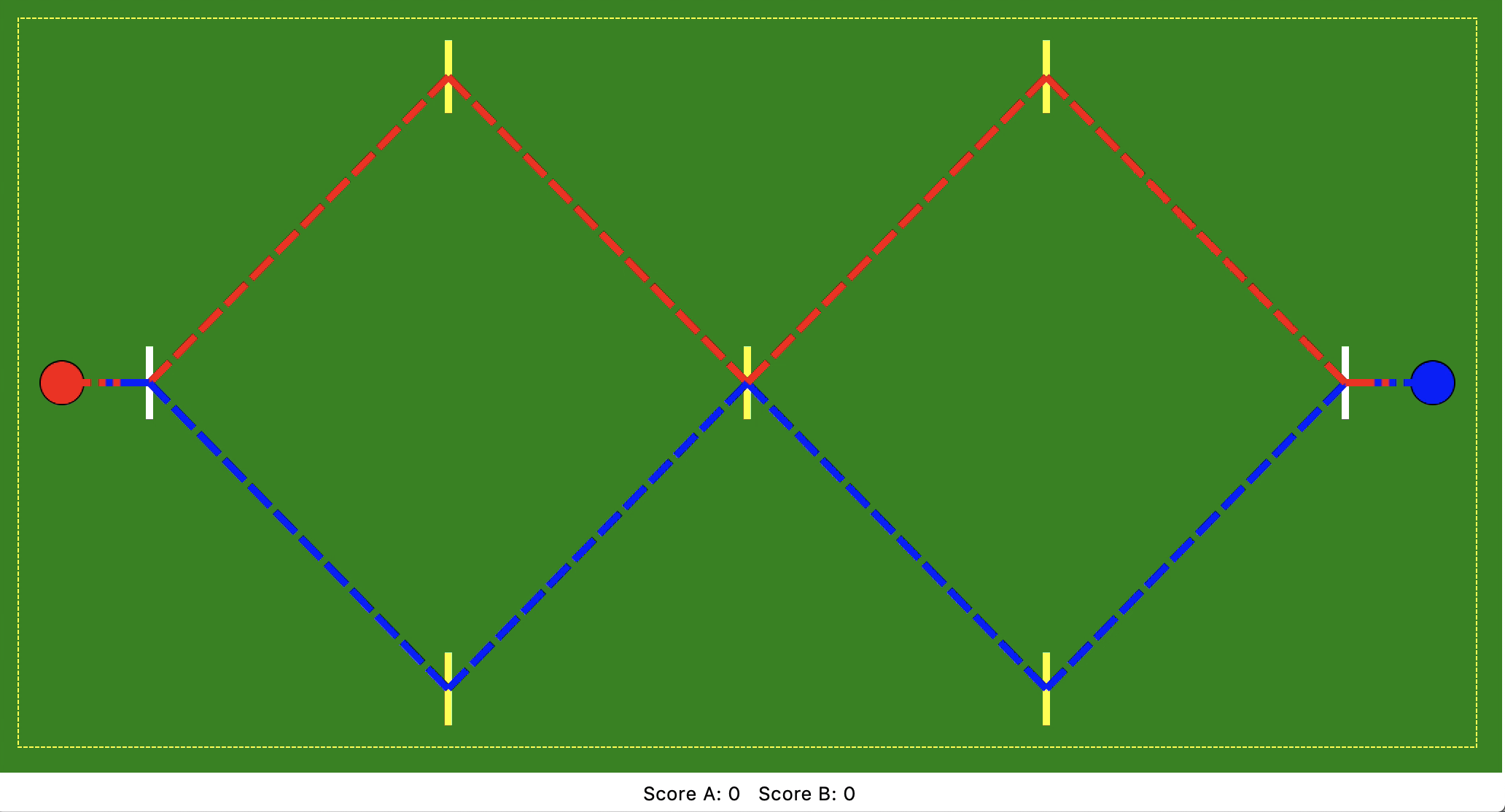
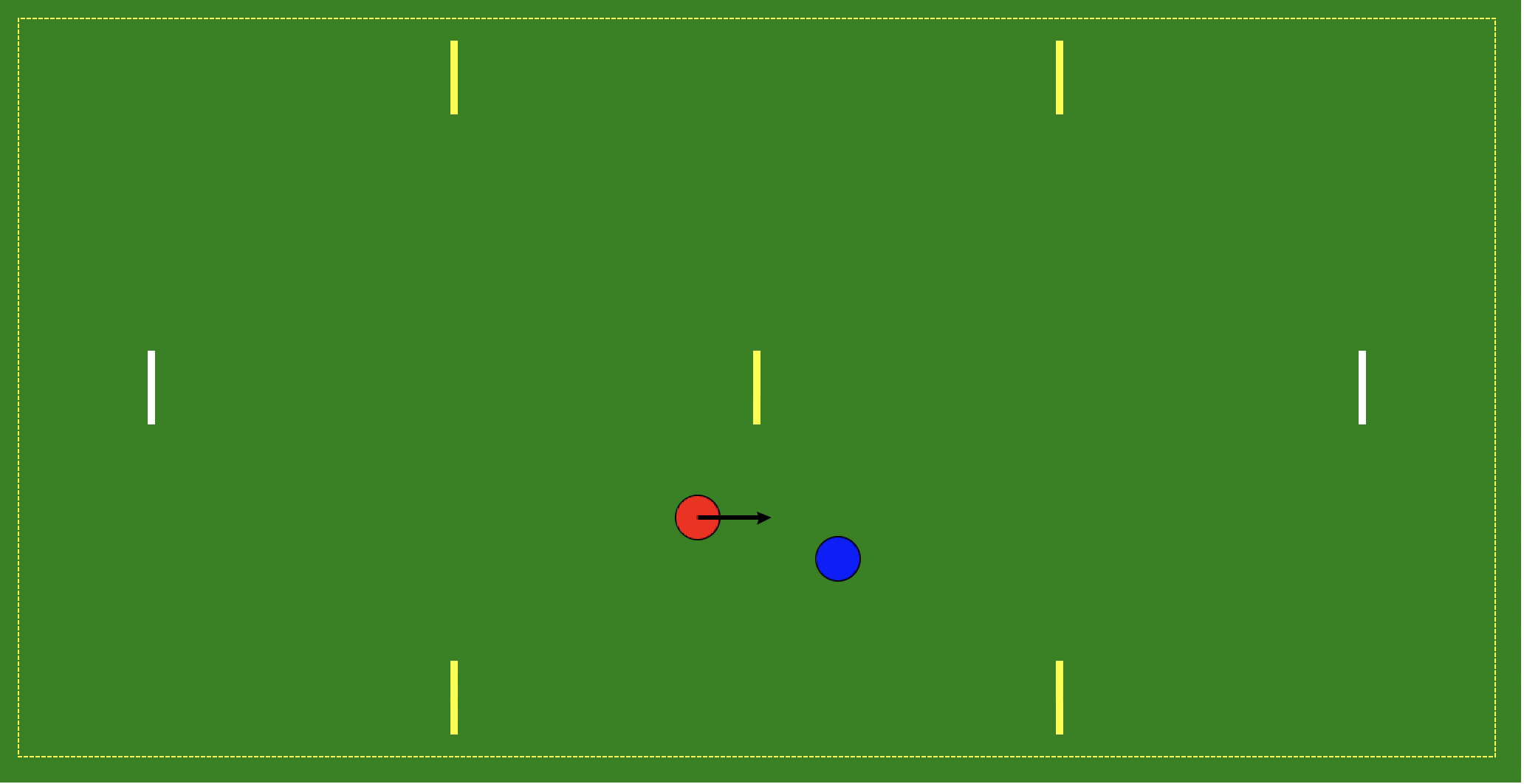
In our version of Croquet, the two players play on a field with seven wickets (drawn as lines) and two balls as shown in the figure below. The dimensions of the field and positions of the wickets are roughly similar to the standard field of Lawn Croquet with nine wickets and two stakes. Each player starts off behind the two white wickets near the edges of the field and are assigned five wickets each that they need to pass through, as shown in the figure below. The objective of our game is to simply go through each of the five assigned wickets before the opponent.
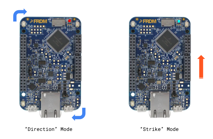
In order to start the game, both players connect their boards to their computers, press the reset button and run the python script on their computers. The system will randomly choose one of the players to start the game, which will then be indicated to both players through their terminal and a Green LED on the board of player 1 and a White LED on the board of player 2. The players would also be able to see the playing field as shown in the figure below. Afterward, the chosen player 1 will place their board on a flat surface and press a button (SW3) on the board to start the “Direction” mode with a Red LED. Now, the player has to slightly rotate their board as shown in the figure to choose the direction they want to shoot the ball in, and press the button again, to confirm. This will update the game window with an arrow and the player will see a Blue+Red LED. Now the player has the option of reselecting their direction (pressing SW3), or to move to “Strike” mode (pressing SW2) to hit the ball. To reselect the direction, the player can rotate their board along the desired direction and press SW3 again. This will keep the last measured direction as the line of reference (shown with the arrow) and add the newly measured direction to it. When the player is satisfied with their direction of the ball, they can press SW2 to go to “Strike” mode with a Blue LED. In this mode, the player needs to jerk the board in the forward direction with desired force, which would be matched with how far the ball moves on the field. After the player presses the SW2 again, the player’s turn would be completed and they would see the ball move appropriately on the game window. If the ball manages to go through a wicket, their score will also be updated. The game state would then be communicated to the other player, who would play their turn similarly. The game would keep going on until a player crosses all the five wickets assigned to them and achieves a score of 5.
For our project, we have also included a “ practice” version of the game which doesn’t require a player to connect to another player in order to play. For this, the player connects their device similarly and runs a slightly different python script. In the practice game, the player gets to play their turn over and over again, till they score the 5 points.
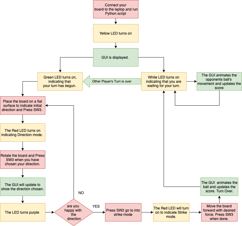
A flowchart showing the overall gameplay is shown below.
System Description
As the final project for our course ECE 3140, we have implemented this game such that the primary game device is the FRDM-K64F boards. After the game is started, the entire computation related to a player’s turn is done on their board, which includes obtaining and interpreting data from the FXOS8700CQ on-board motion sensor, using the buttons and LED on the board as I/O, calculating the entire movement of balls in a turn, and communicating the updated game state to the computer over serial. The computers of the players play a minor role in supporting the game by providing a simple graphic display that the user can look at during their turn which is updated using the game state received from the board over serial, and providing a communication platform between the two players through Transmission Control Protocol (TCP).
The software stack for this project consists of the Keil 𝜇vision project that is loaded onto the FRDM-K64F board and the python scripts to be run on the player’s computers. The files in the overall project are as follows:
- Keil 𝜇vision project
- Main file executed on the board : main.c
- All the functions related to the gameplay: game.c, game.h
- Serial communication with the computer: uart.c, uart.h
- Set up I2C and read/write functions: 3140_i2c.c, 3140_i2c.h
- Obtain and interpret FXOS8700CQ data using I2C: sensor.c, sensor.h
- GPIO functions for LEDs, buttons: utils.c, utils.h
- Python scripts
- Helper python library to display window and animations: project_window.py
- Script to be run on server computer for multiplayer game: project_server.py
- Script to be run on client computer for multiplayer game: project_client.py
- Script to be run for practice, solo game: project_practice.py
Gameplay
The FRDM-K64F boards of both the players execute the overall game as shown in the flowchart below. In order to distinguish between different segments of the gameplay, we have created different game modes (for eg. GAME_BOOT, PLAYER_STRIKE, etc.), each of which have their own defined function in game.c. In the main file, we have programmed an infinite loop, which repeatedly calls appropriate functions for the current mode. The update of current mode to the next is handled inside the mode function itself. At the start of execution, the board first establishes communication with the computer by waiting for the name string “CroK64” and then sends it’s board ID back to the computer (‘A’ or ‘B’). As it can be seen in the flowchart, the game then enters the various modes that have the following broad purposes:
- GAME_BOOT: This is the first mode that the board gets into, where it simply waits to receive the initial game state from the computer. Once received, the board determines from the state whether the player has the first turn by checking if the state matches its ID, and accordingly moves to PLAYER_START or WAIT_TURN. This mode is shown on the board by a Yellow LED.
- PLAYER_START: This mode implies that it is the player’s turn, and is indicated using a Green LED. In this mode, the player can place their board properly, and press the SW3 button to select the initial direction of reference. When the button is pressed, the board records the first reading from the magnetometer over I2C and moves to PLAYER_DIR mode.
- PLAYER_DIR: In this mode indicated by the Red LED, the board first waits for the player to rotate their board with respect to the direction selected in PLAYER_START. Once the player confirms the direction by pressing SW3, a Purple LED turns on, the board records another reading from the magnetometer, and computes the angle of direction from the change in magnetic heading. This direction is the measured angle with the positive x-axis as reference for the red ball, and the negative x-axis as reference for the blue ball. The direction is then displayed on the game window on the computer as an arrow, by sending an updated game state over serial. Now, the player has an option of either reselecting the direction, or moving to the PLAYER_STRIKE mode. To reselect, the player can press SW3, after which the board records a new reference magnetometer reading, and goes back to PLAYER_DIR mode. If SW2 is pressed, the game moves to strike mode.
- PLAYER_STRIKE: This mode, indicated by a Blue LED, is for the player to hit the ball by quickly moving their board in the forward direction. Right after entering this mode, the board continuously measures the acceleration of the board till the player presses SW2 again. From all of the readings, the maximum acceleration is calculated and used to determine the distance the ball will move in the direction selected by the player. Once the final position of the ball is calculated, the board checks if the ball collides with any wickets, edges or the other ball in its path and also if the ball manages to pass through the appropriate wicket and score. This movement is shown on the game window by sending the game state with the new ball location. After movement is complete, the game moves to PLAYER_DONE.
- PLAYER_DONE:b This mode simply determines whether the player wins the game in their turn and accordingly sends the game state to the computer. If the player wins, the game is over and the board moves back to GAME_BOOT to start the next game. Otherwise, the next mode is WAIT_TURN.
- WAIT_TURN: In this mode, the board waits for the other player’s turn to be over by waiting for the computer to resend the updated game state. The board can enter this mode either from GAME_BOOT directly, or after finishing the turn in PLAYER_DONE.

Magnetometer and Accelerometer Data using I2C
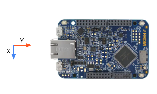
In our game we use the FXOS8700CQ 6-axis motion sensor on the FRDM-K64F to measure movement of the board and map it to the movement of the player’s ball. The sensor consists of an accelerometer and a magnetometer and communicates with the K64 microcontroller using I2C over the I2C0 channel. With the help of the datasheet and other libraries, we first tried to implement our own I2C bare-metal driver that can simply read and write to the required sensor registers. However, after not being able to obtain reliable values using our driver, we set up the I2C communication using the library provided by the TAs that builds upon the FSL library from the NXP SDK for our microcontroller. The files 3140_i2c.c and 3140_i2c.h were used directly from the library, and with the help of 3140_accel.c and 3140_accel.h and the datasheet of the sensor, we implemented our own files sensor.c and sensor.h to obtain the accelerometer and magnetometer values from the sensor and interpret them appropriately. This involved configuring the sensor to ‘Hybrid’ mode, setting up the data rate to 200Hz for rapid read, and configuring high precision of the values. Functions from these files were then used in the game file to obtain the absolute acceleration and magnetic heading along the x, y, and z axes. These axes of the sensor with respect to the FRDM-K64F board are shown below.
The magnetometer in the FXOS8700CQ sensor was used to measure the direction of the board in PLAYER_DIR mode. This direction is the absolute yaw angle of the board when it is placed on a flat surface, determined by the following formula: angle = arctan ( y / x ) where x, y, are the magnetic heading values read from the sensor along these axes. Since the calculation involves a ratio, the raw magnetometer values were used. The two yaw angles measured at different times were then used to find the relative angle of rotation of the board, which was selected as the direction of movement of the ball. We faced a few problems with angle measurement using the magnetometer, which often gave unreliable magnetic heading values. Given the sensitivity of the sensor, the measured values get influenced by the presence of any magnetic field in proximity. We tried a few hard-iron, soft-iron calibration methods for the sensor which were unsuccessful, and we now average 5 consecutive magnetic heading values to get a more stable result. Eventually, we realized that if we keep the board at some distance away from our computers, the sensor values obtained are reliable enough for the game. We also added an option to reselect the chosen direction while playing so that the player can correct a faulty angle measurement.
The game uses the FXOS8700CQ accelerometer to measure the maximum strike force by the player to calculate the maximum distance moved by the ball. This was the maximum acceleration achieved in the positive y-direction of the board in a period of time (moving the board forward between two SW2 button presses). The sensor was configured to measure acceleration in the +/-4g range with 0.488mg precision based on the datasheet. The acceleration in this range can be obtained in units of g by dividing the raw value by 2048. We then mapped the acceleration to the distance moved by the ball, with a factor of 100, such that 1g acceleration = 100 pixels on the game field. We determined this factor by testing the game, and keeping the maximum possible distance a ball can move in a player’s turn to be 400 pixels (4g). Unlike the magnetometer, the values from the accelerometer were fairly reliable and produced the expected result when we moved the board with varying force.
GPIO Utilities
The microcontroller’s general-purpose input output (GPIO) module was used to control the RGB LED and interpret the data from the Push Button Switches on the FRDM-K64f board. The implementation can be found in the utils.c and utils.h file. The LED pins were set up as GPIO outputs. The Port Output registers [PSOR, PCOR, PTOR] were used to create multiple helper functions that turn on, toggle and turn off each of the LEDs. Different combinations of the LEDs were used to indicate the mode to the user. The SW2 and SW3 push button switches on the board were configured as GPIO input and to check when the player has pressed it. The Port Data Input register only updates if the pin interrupts are enabled. The interrupts were generated on the rising edge, so that they would be generated when the player releases the button after pressing it. This was done primarily so that only the final direction is recorded in direction selection mode. Most of the time the game flow needed to wait until a button was pressed. So, the Interrupts Status Flag was constantly polled until an interrupt was generated. The flag was also cleared before waiting for the button to ensure that if the button previously pressed my mistake it is not counted.
Game Computation
Ball Movement
The game window consists of a 1000x500 pixel field along with seven wickets whose positions are constant. The start positions of both the balls are randomized in each turn and interpreted from the initial game state. The final position of both the balls after a player’s turn are determined by that player’s board and sent to the laptop via the game state. The actual calculation takes place in the PLAYER_STRIKE mode in the game.c file. First, the total distance to be moved is calculated using the data from the FXOS8700CQ accelerometer as described in the previous section. The direction selected by the player is used to determine the movement along the x-axis and y-axis. The direction is stored as the angle (radians) with respect to the positive x-axis. The cosine and sine functions of this angle are used to get the distance moved along each axis and the coordinates of the final point. However, the field boundary, wickets and the other ball deflect the ball if a collision occurs. The final position is modified if such a collision occurs. A recursive function is used to check if any of the three types of collision in its path. The ball is deflected from the nearest collision. Once the nearest collision point and the deflection path of the ball is determined, the game state is transferred to the laptop to show the ball movement until the deflection point. The same function is called to check for collisions in the path to the new final position after deflection. This cycle repeats until the movement is collision free, this is the final position of the ball after a turn.
All collisions are perfectly elastic except the opponent ball collision. Thus, the distance moved by both balls in the entire turn is equal to the total distance the player’s ball was originally supposed to move. The score is checked for every movement and updated accordingly. Another approach to handle collisions would involve tracking the ball position in each frame. This means the game state string needs to be updated for every animation frame and the board simply checks if it is colliding with an object at that instance. While it was an easier approach, it was disregarded because of the high depending on serial communication speed and to ensure that the main computation is handled by the board. The entire game window is mapped by pixel coordinates. The axes of the game window are not conventional. The origin is in the top left corner i.e. the x coordinates increase towards right and the y coordinates increase downwards. It is similar to the fourth quadrant in a graphical system. All calculations for the ball movement and collisions take this into consideration.
Boundary Deflections
The ball can be deflected if it collides with any of the four field boundaries (edges). This happens when the final position of the ball is outside the 1000x500 pixel game field. There were eight different cases of boundary deflection – four for single deflection, one from each boundary; and four for double deflection from two adjacent boundaries. Once the deflecting boundary was confirmed, the point of deflection was calculated using the equation of the ball’s line of motion and the fixed coordinates of the boundary (eg, x = 0 for the left boundary). In case of double deflection, the boundary that deflects first needs to be determined. The edges deflect the ball only if its center was colliding. Once the ball collides with the boundaries, then it is deflected following the laws of reflection. To determine the new final position of the ball, the final point was reflected about the boundary line. In the case of double deflection from a boundary, the new final point would also be outside the game field, which would be handled in the next iteration of the function to check collisions. If the ball deflects from a corner point, it retraces its path.
If you are unable to see the gifs below, please use a browser other than Google Chrome.
Video: Double Boundary Deflection
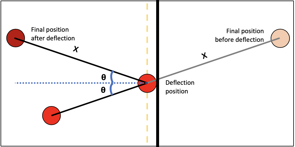
Figure: Diagram explaining single boundary deflection
Wicket Collision
A ball passes through a wicket only if the entire ball is inside the wicket since they resemble actual hoops which are stuck into the ground. If the ball hits the corners of the wickets, it is deflected. There are seven wickets on field and checking if the ball collides with every single one (the ball hits the either corner of the wicket) would be time consuming. So, the wicket which could be in the ball’s path was narrowed down and then checked for collision. Depending on the direction of movement, the x position of the wicket (5 possibilities) that is in the range of the ball’s path were narrowed and the wicket which the ball could cross in the y range was checked for collision. The wickets were considered as vertical lines and therefore the ball is simply reflected from the wicket after determining the collision point. Deflection from wickets exactly along the vertical line has not been implemented.
Video: Deflection from the wicket
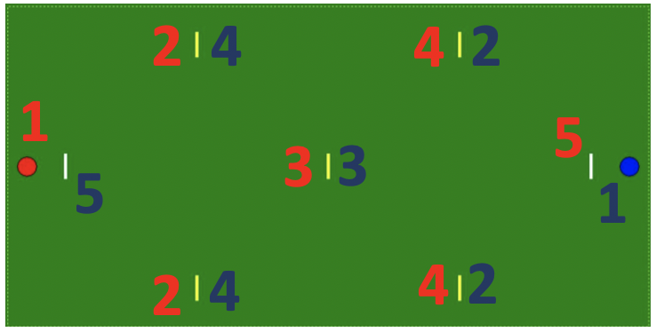
Figure: The order in which wickets are checked. The Blue ball moves towards left and the red ball moves towards right.
Opponent Ball Collision
If the player’s ball hits the opponent’s ball, both of the balls move half the remaining distance of the player’s ball after the collision. First the ball coordinates are examined for a possibility of collision. To check for collision, the shortest distance (perpendicular) from the opponent ball’s center and the player ball’s path is calculated. If this distance is less than the sum of the ball’s radii, a collision is detected. The ball should be deflected before it reaches the point with the shortest distance. The deflection position is the point on the path at where the distance between the two centers is equal to the sum of their radii. After collision, the balls move along the line joining their centers. After this movement is determined, the recursive function is called again to check if either of the balls face any deflections in their path, and is then shown accordingly.
Video: Collision with the opponent's ball
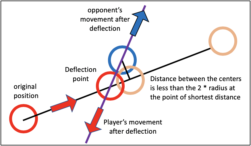
Figure: Diagram explaining collsion of the two balls
Score
Players need to move five wickets in a certain order depending on their start position shown in the figure below. Each wicket is worth one point, the first player to get five points wins the game. The player’s score current score is used to determine which wicket they are supposed to pass the ball through. The score is increased only if the entire ball goes through that particular wicket. For each movement of the ball, the score checked right before sending the game state to the laptop and updated if required. Each player can earn one bonus point once a game by hitting their opponent’s ball. After earning the bonus point they can move on to the next wicket. A player does not score a point if the ball passes through the required wicket as a result being hit by their opponent. When a player scores the fifth wicket, the game state is updated to reflect their win and the game is over.
Game State
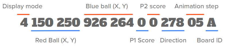
The game state is a 21-character long string, which is the only data transmitted between the board and the laptop and between the two player’s laptops. The python programs send the initial game state to the boards, after which the boards compute the game state. The first 20 characters of the game state are digits and the last character is the BOARD ID of the board whose turn it is. The structure of the game state is as follows:
- [0] : Display mode; there are five different display modes:
- '0' for when the current player's turn has been compeleted
- '1' when player 1 wins the game and the game is over
- '2' when player 2 wins the game and the game is over
- '3' direction selection mode to show arrow on the game window
- '4' deflection occured, current player's turn not yet over
- [1-3, 4-6] : Player 1 ball's 3-digit (X,Y) coordinates
- [7-9, 10-12] : Player 2 ball's 3 digit (X,Y) coordinates
- [13] : Player 1's current score
- [14] : Player 2's current score
- [15-17] : Ball direction, in radian * 100
- [18-19] : Animation steps, total number of frame in which the given movement is shown
- [20] : BOARD_ID of current player
Every time the board receives the game state string with its BOARD_ID at the end, it is converted to digits and the game variables are updated. Once the next position of the ball or the direction has been computed the new game state with. The updated game variables are sent to the board through the game state. On the laptop, the game state string is interpreted by the python program to update the new position of the balls in the game window and sent to the opponent's laptop when required.
Serial Communication
The Serial protocol, an asynchronous communication protocol has been used to transmit the game state between the board and the laptop. The K64 microcontroller’s Universal Asynchronous Receiver/Transmitter (UART) module was used to enable serial communication. A bare-metal driver has been implemented to send data over UART0 in the uart.c and uart.h files. The standard serial baud rate of 9600 bits per second was used to send the game state one character at a time. The TA tutorial was used as a guide for sending data over to the serial line. Our own interrupt-based implementation was used to receive data. The Receiver Full (RIE) interrupt and the Overrun Error Interrupt (ORIE) were enabled. The NVIC interrupt handler, used to read and store the data received, expects strings that end with ‘\n’ characters. It does not indicate that a string has been received until the ‘\n’ character is read. The board’s OpenSDAv2 port, which is connected with the primary serial port interface signals, is connected to the laptop using a USB cable. The python script on the laptop receives the 21 byte game state on the serial line.
Internet Communication through TCP
An important feature of our game is that it can be played by two players located anywhere in the world (one of the team members is currently in New Delhi, India, and the other is in Dubai, UAE). We achieved this by connecting the two players over the internet through Transmission Control Protocol (TCP). At first, we had tried to establish direct communication between two boards, using the lwIP stack built in the NXP and the Kinetis SDK. We tried to use MQTT to connect the two boards to a common MQTT broker (adafruit.io) and thus enable them to send information to one another. With no success, however, we decided to instead use the computers to communicate over the internet, since the boards will have to connect to them to display the game anyway.
Currently, our python scripts use python’s Sockets library to send TCP packets from one computer to the other. Instead of building a dedicated server to which all the player’s computers can connect, we have used one of the computers in the game as a TCP server and the other as a TCP client (to simplify and minimize the amount of the project implemented on the player’s computers). This is why there are two different python scripts to be used to play a game, project_server.py and project_client.py. In order to play the game, the scripts need to be edited to include the public IP address of the computer that runs the server script, and the player running the script will have to enable port forwarding on their internet router. Port forwarding ensures that any messages coming to the public IP on a specific port would be automatically transmitted to the player’s computer. No port forwarding needs to be enabled, however, if the two players are connected to the same LAN, and then the server’s local IP address would be used (that starts with 192). Such an approach to an internet-based multiplayer game would present problems with scalability, but it was sufficient for us to run our simple game based on the FRDM-K64F board.
Python
In order to run the game on the player’s computers we have created four simple python scripts to display the game window and communicate with the board as well as the other player. As described above, serial communication is used to send and receive the game state from the board. Python’s PySerial library is used to encapsulate the access for the serial port to which the board is connected. Over the serial line, the game state is communicated encoded as bytes and needs to be decoded into ASCII characters before use.
To send the game state as TCP packets over the internet to the other board, the Python’s sockets library was used. The project_server.py script creates a TCP socket (socket.SOCK_STREAM) which acts as a server and waits for connections (listening socket) while the project_client.py script establishes connection with this TCP server.
The game state is transmitted as a byte stream between the client and the server. The game window is displayed using tkinter, python’s standard GUI package. It is an instance of the Window class implemented in the project_window.py module. The game field, balls, wickets and direction arrows are drawn using elements in tkinter’s canvas object. The game window also displayed the score and winning message as a label at the bottom. The animation of the ball movement is created by the simple technique of moving the ball by a small distance between each frame. The frame rate is modified throughout the animation to mimic movement of a ball on a grass field .The number of frames to display the movement is inferred from the game state. Apart from this, helpful status messages are also printed on the terminal. The jimner library was used to display ASCII Art for the game title. The project_practice.py script runs a single player version of the game and does not implement the TCP protocol.
On running the python script, it first establishes a connection with the board over serial and obtains the board’s unique BOARD ID. The python scripts are independent of the board connected to it. Next, the program tries to establish communication with the other player’s laptop. As soon as the server and client computers are connected, the server sends its BOARD ID to the client and the client does the same. Then chooses either of the BOARD IDs to play first and creates the initial state with the last character as the chosen BOARD ID. The server sends this initial state to the server’s board and client, who transmits it to the client’s board. The game window is created displaying the initial positions of the ball. Then the program, whose board’s turn is first, waits for the board to send the updated game state. The game window is updated every time a game state is received. The game states that show movement of the ball or a player win [mode 0, 1, 2, 4] are also sent to the other laptop, where the game window is updated to view the opponent’s moves. Only the final game state [mode 0, 1, 2] is sent to the opponent’s board with its BOARD ID to indicate the start of their turn or in the case of a win the end of the game. Once the game is over, the TCP socket connection is cleaned up. The practice script follows a similar program flow.
Testing
We have implemented this project with a “divide-and-conquer” approach. Since the game consists of various separate elements, as they were described in the previous section, we first tried to implement and test all of them separately before integrating them into the overall project. For example, with the help of the TA tutorial video, we implemented our serial module which can send and receive information to the computer, along with a separate python script using PySerial, to test and ensure that the communication works properly and no data is lost. Similarly, we modified the provided I2C library and verified the values read from the FXOS8700CQ sensor by printing them to a serial terminal while changing the orientation of the board. With the python segment of the project as well, we first wrote different scripts for TCP communication using sockets, and also created the game window using tkinter, etc. before creating a compiled project.
In this way of implementation of the project, we could be sure of the functionality of different parts of the game before testing it all together. After compiling everything into the game, our primary method of testing the gameplay was playing it over and over again: we ran the game, checked what went wrong, fixed that, and ran it again. This way we were able to successively correct several mistakes in our code till the whole game seemed to run smoothly. When the normal gameplay seemed to run with no errors (with serial, TCP, sensor, etc.), we tested the game by forcing several corner cases.
Some of the techniques that we used to test various parts of the game are as follows:
- Implementing a separate single-player mode so that both of us could test the game individually. We have now included this mode in the game as a “Practice mode” which anyone can play by themselves.
- Printing messages over serial. We also edited the game_state string read by our python script to include some game variables from the board that needed verification.
- Debugging using LED by glowing it at various instants during code execution.
- Using Repl.it to verify logic and functionality of various functions used in the game, out of the game’s context.
We have tried to test this project very thoroughly, and here are few of the various problems and corner cases that we faced and corrected (in no particular order).
- At first, the direction of ball movement was calculated with the positive x-axis as the reference. However, since the pixels on any GUI are such that the top-left corner is the origin, we changed the measurement of direction to be in the fourth quadrant in the Cartesian plane. Also, after playing the game with the Blue ball on the right, we realized that it was much more natural for the blue ball to have the negative x-axis as reference, and we changed the measurement accordingly.
- While testing the FXOS8700CQ sensor, we found that it returned up to ten equal values on consecutive reads. We fixed this by configuring the sensor such that it outputs at a higher data rate (200Hz).
- During the gameplay, we found that if we somehow press a button by mistake at an inappropriate moment, the board doesn’t wait for it to be pressed the next time, and automatically moves to the next mode. This happens because whenever we press the button, its flag is set, which we don’t clear till we read it. So we introduced another function to clear the flag, right before the board starts waiting for the player to press the button.
- The movement of the ball as explained in the last section was also a result of several design upgradations through testing. Initially, we were using a non recursive function to show only the player’s ball movement. This first was updated to show deflections from the boundaries, which had a literal ‘corner case’ in which the ball deflects from two adjacent boundaries. Then we implemented collisions of wickets for which we made the movement recursive, and finally the collision of the two balls which was done by making all the other deflection functions generic for either ball. There is still a rare corner case where the balls collide with each other twice in the same sequence of movement, by being deflected by other obstacles. This case has not been implemented due to mathematical complexity.
Work Distribution
As the project has been implemented in segments, both of us productively took up different features to work on, before bringing them together. For example, Aryaa implemented the GPIO and sensor input, while Krithik worked on serial communication. Once we had all the small features ready we wrote the entire game play on the Windows laptop. We used Zoom meetings to write crucial parts of the code such as the algorithm for the movement of the ball and also tested the entire game play together. This was also necessary because our game involves both the boards. After thoroughly testing and completing the project implementation, we also divided the other submission elements among us. Aryaa worked on editing the video while Krithik wrote the README.md document, while the website and video content was also equally distributed.
Resources
Datasheets
- K64 Reference Manual
- FRDM-K64 User Guide
- FXOS8700CQ 6-axis sensor
FXOS8700CQ Sensor
Serial Communication
- https://maker.pro/pic/tutorial/introduction-to-python-serial-ports
- https://gist.github.com/johnschimmel/95bd3d94799717d4ace5
- https://learn.sparkfun.com/tutorials/terminal-basics/connecting-to-your-device
TCP/IP using Sockets and Port Forwarding
- https://realpython.com/python-sockets/
- https://www.noip.com/support/knowledgebase/general-port-forwarding-guide/
GPIO
Croque
Other Helpful Resources
- https://dzone.com/articles/mqtt-with-lwip-and-the-nxp-frdm-k64f
- https://community.nxp.com/thread/446871
- https://community.nxp.com/docs/DOC-344866
- https://usermanual.wiki/Document/lwIP20TCPIP20Stack20and20Kinetis20SDK20Integration20Users20Guide.1442194903/view
- https://github.com/ErichStyger/mcuoneclipse/blob/master/Examples/MCUXpresso/FRDM-K64F/FRDM-K64F_lwip_lwip_mqtt_bm/source/lwip_mqtt.c
- https://confluence.cornell.edu/display/ece3140/I2C+for+the+K64F