Introduction
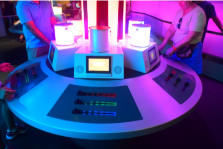
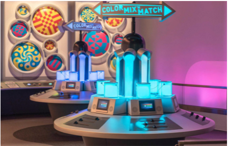
Our game takes inspiration from an exhibit that Samantha encountered in 2017 in EPCOT at Disney World. At the time there was an exhibit called colortopia featuring all sorts of games relating to color including a game called color mix-n-match. In this game a color is randomly generated and displayed in the consoles of pouring paint buckets in the center (as pictured). The goal is to play with the three sliders on the console that change the intensities of red, green, and blue respectively in order to get the color of your paint bucket in front of you to match the ones in the center.
In our color wheel matching game, there are 2 LEDs in our system, one that has a randomly generated color displayed, and the other is one that the player controls the RGB values for. The player’s goal is to match the color of their LED to the provided color. If they get it right within a certain accuracy range, the LEDs will flash green. Then the next round will start after a pause with another randomly generated color. For this game, we employed both the LED lights and the capacitive touch sensor on the board. In addition to that, we implemented two other external peripherals that are connected to the board, a simple button and another LED. The button allows the player to switch the capacitive touch sensor between controlling the intensities of the onboard Red, Green, and Blue LEDs. In the end, we were able to get our game fully functioning.
Overall, this was a really fun and challenging project that had us not only apply our knowledge that we gained from this class throughout the semester, but also learn about some really interesting concepts such as utilizing the touch sensor, adding peripherals like the external LED and button, and learning and implementing PWM with the LEDs.
System Overview
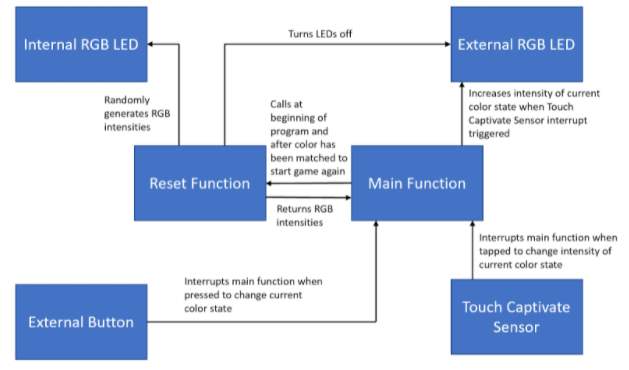
Our system makes use of both on-board and external peripherals to achieve a working game. We used code from previous labs as a foundation in addition to utilizing pulse-width modulation (PWM) for achieving the additional LED functionalities of controlling the precise intensities of both the onboard and external LEDs and generating random colors. The TSI_v4 SDK example code was also used to allow our game to read in taps from the capacitive touch sensor. We also make use of an external button to switch the capacitive touch sensor between controlling the Red, Green, and Blue LEDs (color state). With all the peripherals integrated correctly, we used the ideas behind the code we developed in previous labs as well as the board manual to allow us to handle interrupts. We didn’t add any significant additional software features like a GUI or website. For processes, we wrote code to handle the different interrupts generated by the button and capacitive touch sensor to change the player-generated LED color. Below, we’ve attached a block diagram illustrating a high-level overview of our system.
Project Video Demo

Detailed Technical Description
Internal and External LEDs - PWM The first feature that we needed to make sure that we enabled was being able to change the intensity of LEDs because without this, the point of our game would have failed since varying intensities of red, green, and blue is what creates other colors. Through doing research and going to office hours, we learned that we could accomplish this through PWM (pulse-width modulation). PWM essentially controls how quickly the LED flashes (faster than the human eye can detect) which makes it seem to us that it is a different intensity and dimness. The aspect of PWM that we change in order to change the intensity of the LED is the duty cycle or what percentage of the clock cycle the LED is on vs off. To do this, we created a struct that stored the necessary PWM information and an array of these structures that contained the different intensity levels that we would set the LED to be at. Having set intensities vs a continuous percentage change was a design choice we made because having these set intensities made it easier for increasing brightness using taps on the touch sensor, being able to set the brightness of the led, and most importantly, for comparing intensities to see if the colors were matched. This is because we only needed to store the index of the intensity array and change that value instead of having to store and modify the percentages themselves.
To make it easier to change/set the intensities of the LEDs, we took the utils.c and utils.h files from previous labs and modified them to suit our functionalities of the internal LED. We created ext_utils.c and ext_utils.h for the external LED. In these files, we initialized the LEDs which included enabling the clock to the applicable ports, setting the PWM clock, setting the mux in the port control registers for each pin to be TPM (instead of GPIO which is what we have done in earlier labs), and configuring the TPM. TPM stands for Timer/PWM Module and we can set the duty cycle of the pulse of the TPM which in turn changes the intensity of the corresponding pin/LED.
In our turn LED on function, we set the intensity to be at max and for our turn LED off function, we set the intensity to be at its lowest. We also implemented increasing the intensity of the LED through adding 1 to the index stored in the color intensity variable and then setting the duty cycle to be the new applicable value from our array of intensities. Similarly we also have a set intensity level which we utilize for randomly generating the color of the internal LED where the input is a randomized value which we modify to have it fall within the bounds of the array, set the duty cycle to be the applicable intensity, and then return the index/color intensity to be stored for use later in determining if the colors matched.
Capacitive Touch Sensor To integrate inputs from the capacitive touch sensor on the board into our system, we used the tsi_v4 example from FRDM KL25Z SDK as a starting point. From the example, we copied over the TSI_V4 driver as well as ones including the LPTMR (low power timer) and GPIO. We also changed our board files with code from the examples to configure the system core clock. In our ece3140-final-project.c file, we took some code from the example to initialize the boot clock, pins, LPTMR, and TSI.
To get the touch sensor working, we first calibrate the electrodes on the board with results from no touches as the baseline. We also set up hardware interrupts and start the LPTMR to trigger the interrupt every 300,000 microseconds (i.e. 0.3 seconds), using BOARD_TSI_ELECTRODE_1 as the detecting electrode for taps. The TSI interrupt handler checks for the correct current measured channel number and makes sure conversion counter value from the electrode is above the sum of the previously calibrated level and a TOUCH_DELTA_VALUE to trigger the code inside. If a valid touch is detected, then depending on which RGB channel the user has selected with the button, one of the external RGB LEDs is incremented.
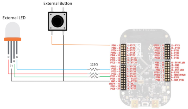
Button In order to implement the external button, we created button.c and button.h that can easily be called in main. Because the button is connected to Port A Pin 1 (as illustrated in the schematic below), we used the Port A interrupts in order to implement the changing of the color state when the button is pressed.
For initializing the button, we created Button_Initialized which enables the functionality of the button as well as the interrupts for Port A. It enables the clock to port A, sets the pin as GPIO input, enables the interrupt to trigger on the rising edge of the button push, and enables the internal pullup resistor.
When the button is pressed, an interrupt is triggered which is handled by PORT_IRQHandler. In the handler, we clear the interrupt flag and then change the value currently stored in colorState. colorState records which color to change when the touch sensor is tapped (0 to change the intensity of the external Red LED, 1 to change the intensity of the external Green LED, and 2 to change the intensity of the external Blue LED), and changes when the button is pressed.
The colorState is supposed to rotate between red, green, and blue, but sometimes a color state is skipped which we believe is due to the button triggering the interrupt multiple times when pressed instead of just once.
Checking Match Because the purpose of the game is to match the color of the external LED to that of the internal LED, we wanted to add functionality to determine whether the user has successfully accomplished the task and indicate that to them. In order to do this, we keep track of the current intensities of both the internal and external LEDs. Because we just sit in an infinite loop since we use interrupts to change the intensity and color state, we regularly check if the intensities of the external LED are within a certain range of the intensities of the internal LED. We determined a good range was to be within 7-10 levels of one another since due to hardware differences in the LEDs, the external one had an overall higher intensity compared to the internal one.
Once each of the red, green, and blue intensities were within the set range, we set both LEDs to just be green, hold that color for a bit, and then reset the game where another randomly generated color is displayed on the internal LED and the external LED is turned off to start.
Timer Originally, we had planned for this to be a time sensitive game and wanted to enable the PIT in order to create a time limit of about 60 seconds. If the time limit is reached prior to successfully matching the colors, both LEDs would turn red instead of green, and then reset the game to the next round/color. Once we set it up just as we had done in prior labs however, the game stopped functioning where we couldn’t change the intensity of the external LED anymore. We went to office hours in order to determine if we would be able to fix this or not where we determined that because of utilizing 6 TPM channels as well as multiple interrupts already that the board might not be capable of handling another timer. Because the timer would have just been a nice additional feature and did not impact the overall functionality and goal of the game, we left it out. We did leave the beginning of our timer implementation (basics of the interrupt and enabling the PIT from previous labs) in our final code and commented it out.
Schematic illustrating how the peripherals were connected to the board (i.e. which ports on the board each pin is connected to):
Schematic for the internal LED from the board manual:
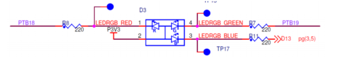
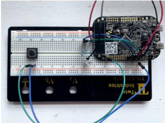
Image of our setup used in order to run the game:
Testing
Our testing procedure involved independently ensuring the functionality of each component of our system as we implemented them, and at each step of integration. For example, once we initially coded the functions to change the intensity of on-board LEDs, we tested the ability for the board to flash non-RGB colors, then moved onto connecting the external LED to do the same thing. When implementing the capacitive touch sensor and button, we had to make sure we implemented the interrupt handlers correctly, so we started small. For the touch sensor, we first tested the ability for the board to register simple tap inputs and toggle an LED, while for the external button, we tested it independently to see if we could read press inputs before integrating it to the rest of our system.
Later on, during integration we would test different components of our system together to meet the goals of our game. The end goal would be for the button, LEDs, and the touch sensor to work together harmoniously, so we made sure there wouldn't be complications between interrupts and that the game functioned as required. To test this, we played full games on the board setup to try to discover any kinks. We tried differently, like a large amount of fast inputs on both the touch sensor and external button. We also tried pressing both the touch sensor and button simultaneously to see if that would cause issues, but it turns out the button has a higher interrupt priority, so in this case, the current color state is changed.
Additional Resources Used
Websites that helped us to learn and implement PWM in order to control LED intensities: https://learningmicro.wordpress.com/controlling-led-brightness-using-pwm/ https://visualgdb.com/tutorials/arm/kinetis/kl25z-rgb-led/ We built upon these ideas in order to implement it for all of the LEDs we used for the project.
Websites that helped us to learn and implement adding a button: https://community.nxp.com/t5/Kinetis-Microcontrollers/KL25Z-GPIO-Interrupt-quot-IRQHandler-quot/m-p/770158 https://community.nxp.com/t5/University-Programs-Knowledge/Push-buttons/ta-p/1124365
Resources used to implement the capacitive touch sensor: The tsi_v4 example from FRDM KL25Z SDK. Code was borrowed from this example to read in taps on the sensor.
Images of Colortopia from Introduction and Video are from: https://dapsmagic.com/2015/11/colortopia-a-new-colorful-experience-at-epcot/ https://razorfoxcreative.com/project/glidden-colortopia-innoventions-epcot/
Images for peripherals schematic are from: https://all-free-download.com/free-vector/download/resistor-symbol-clip-art_10359.html https://webstockreview.net/image/button-clipart-push-button/315850.html https://www.circuitbread.com/tutorials/how-rgb-leds-work-and-how-to-control-color
Samantha’s friend Grace who let us use some of her electronic components to set up our peripherals!
And of course the KL25 Sub-Family Reference Manual!
Work Distribution
We both worked together on generating different project ideas and met to do so and write the proposal.
For the project, we divided up the initial steps of researching and implementing the different peripheral components of the system. Samantha focused on controlling the intensity of the on-board LEDs first, while Chris attempted to implement an analog slider using the touch sensor. Later on, while the touch sensor was proving to be difficult, Samantha continued onto the task of connecting the board to an external LED and button. During this time, we would touch base over zoom every day to update each other on our individual process and provide feedback and insight to each other's work. After we got the sensors working, Samantha focused on incorporating a timer process into the color matching game and getting the game up and running.
Regarding testing, both members participated in the testing process, making sure to test each other’s components in the system.
Chris worked on setting up the website, and Samantha filmed and edited the video. Finally, both members of the team worked on writing the final website material.
One of the tools we used to facilitate collaboration is git. This way, we are able to share versions of the code with one another and have records of previous versions in case there was some sort of error that was introduced when integrating our code together. We also used Google Docs for collaborative editing the text for the website and the script for the video.