Introduction
Welcome to Numbers Trivia! This is a game where all the answers are numbers. We decided to create an interactive game because we wanted to see how we can put we learned this semester to usage in the real world. For our interactive game where the player uses the capacitive slider to answer questions that show up on the terminal via UART. The player can toggle the blue LED by keeping a finger on the slider. To answer a question, the player must toggle the LED. When the LED turns on AND off (one time each), the answer is 1 (So on and off 2 times each changes the answer to 2). The player must toggle the LED a correct number of times (no more no less), which changes with each questions, within a short period of time to answer the question correctly. The game ends when all questions have been answered and an ending statement with a final score is shown on the terminal. This game was fun to create and play. We were able to successfully use our knowledge of the board to create this game, and we also learned valuable board skills such as using UART and using the touch slider.
System Overview
The FRDM-KL25Z board is connected to the computer using a USB port. When the program runs, a print to screen instruction is shown on the terminal explaining the rules of the game. A short delay is set so the player can read the instructions before the game starts. The game starts when the first questions is shown on the terminal. The player will use the slider to answer the question. The slider will toggle the blue LED when touched. To answer a question, the player must keep their finger on the slider to toggle the blue LED. The player must answer the question within a short period of time. A statement will then show up on the terminal to tell the player if they answered correctly. When all the questions are answered, a statement will show up on the terminal telling the player the game is finished.
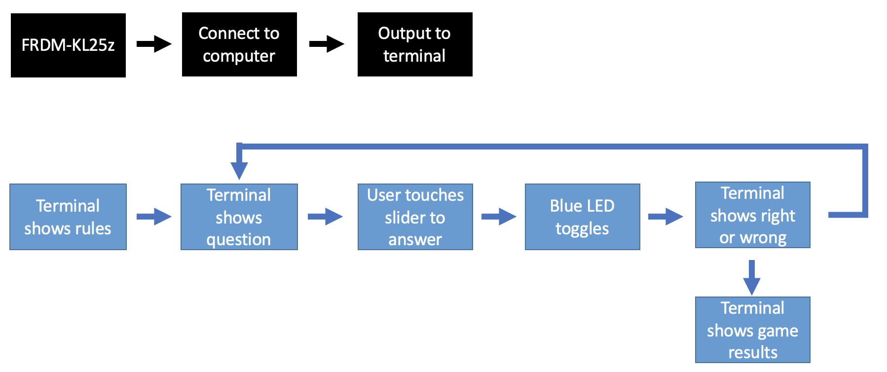
Figure 1: System Overview flowchart
Project Video Demo
Detailed Technical Description
This project uses the FRDM-KL25Z board which communicates through UART protocol to a python script which allows the user to play the game. We used the TSS (Touch Sense Sensor) on the board that reads TSI (Touch Sense Input) to detect the answers to the respective trivia questions. We first designed a TSI0_IRQHandler() function that handles touch input so that the blue LED can be toggled every time the user touches the TSS on the board. Then our program is organized into helper functions which assist in UART communication, printing to the terminal, selecting the appropriate question, and checking whether the user got the question right or wrong. First we calibrate the TSS circuitry and UART communication (init_uart()) within the main function, then we use questions_print() to display the question based on the starting question index. Then we loop through the array by using the helper question_select() to display the appropriate indexed question that is next in line. Questions on the terminal through the python script that the user will have to answer within a certain time frame. We use delays and counters to check how many times the LED is turned on and off during the answering time period. The questions_check() method checks to see whether the user input of how many LEDs they have on matches the correct answer. Then a response based on whether they answered correctly or not is displayed on the terminal. The helper function final_score() calculates the score when the game ends and displays it. After the user has completed all questions the program outputs "Good Job! you finished with a score of: x/10" so that the user knows to either click the reset button to start over or press CTRL+C to exit the program.
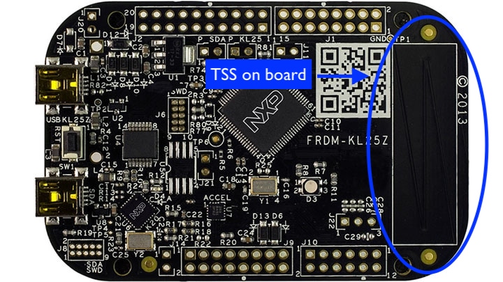
Figure 2: Location of the TSS on the FRDM-KL25Z
Testing
To test our program, we first made sure that the slider and UART worked correctly separately before combining the two codes. For the slider, we tested to see if a LED of our choice (red, green, or blue) would toggle, turn on, or turn off, when the slider was touched. For UART, we tested to see if it would print statements with and without "\n" correctly.
To test the game, we tested zero input by making a question in which zero was the correct answer. WE played a round where we toggled the LED correctly for each question, to make sure to program worked as intended. We also tested if the program would determine the answer to be wrong when the LED toggled more and when it toggled less than the correct amount of toggles. We both played the game a few times each, each time getting different amounts of questions correct, to test if at the end of the game our score is correct.
Additional Resources Used
All of the following sources have been modified by us to fit our program's needs
util.h and util.c from ECE 3140/CS 3240
Professor Napp's serial_example.c and python_serial.py
Driver files fsl_lptmr.c, fsl_lptmr.h, fsl_tsi_v4.c, and fsl_tsi_v4.h from frdmkl25z_driver_examples_tsi_v4_normal (example project in MCUXpresso)
Work Distribution
We collaborated through zoom and google drive. We shared out ideas for the final project on zoom and edited it on a google doc. When writing the code for the project, we worked on the project independently then shared what we had accomplished through zoom and shared screen. We constantly shared ideas on how to approach problems while on zoom when our code was not working, and we both actively searched for solutions. For the webpage, we divided the webpage sections up equally and then went back and edited each other's sections when we were done. For the video demo, Hannah explained details of the project and Amy showed and explained the project when run. Fortunately, there were no issues with the team throughout the project and we collaborated well with equal contributions.