In this page you will learn about detailed technical aspect of IntelliGlove and testing procesures we used to determine the correct functionality of the system.
Sensor Design
We developed customized sensors that are able to measure changes in angles of the five base knuckles by sensing the stretch force and flex applied by knuckle when the finger is bent around it. These sensors are made of pressure-sensitive conductive sheets (velostat) and copper conductive fabric. The figure below shows the basic structure of the force sensor.

The reason we chose velostat is because it is a lightweight, flexible, and durable material that is commonly used in electronics and robotics as pressure-sensitive resistor. We have two copper conductive fabric layers that serve as electrodes to be in contact with the velostat and form a sandwich structure. The copper conductive fabric we have chosen offers not only excellent electrical conductivity, flexibility, and durability but also remarkable heat resistance, enabling us to solder wires directly onto it for a secure and stable connection without any risk of conductivity loss. After the conductive layer has been applied, electric tape is used to cover and secure all of the layers. This serves the dual purpose of providing additional stability and protection while also reducing any electrical noise that could potentially interfere with the accuracy of the analog readings. The dimensions of the velostat layer in our design are roughly 5cm by 1.8cm, while the two conductive layers have been sized down to 3.8cm by 0.9cm in order to prevent any accidental shorting.
Circuit Design
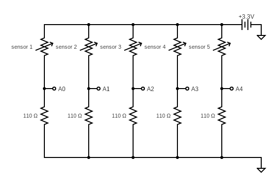
The resistance of the pressure sensitive conductive sheet would decrease correspondingly as more force is applied to it. Based on this property, we used a voltage divider circuit that connects the force sensor and a load resistor to convert change in resistance value to voltage analog reading. Based on testing, we decied to choose a load resistance of 110 ohm to achieve a more suitable voltage range.
ADC
Since we need Analog to Digital Converter (ADC) to convert analog signals into digital data that can be processed, we found example ADC polling code from NXP community website. The adc.h file includes the function "adc_init" that initializes the ADC of a board. In the function, clocks for both the ADC and the Port B are enabled to allow data to be received from the input pins. Then, the ADC is calibrated by calling "adc_cal" to ensure that it provides accurate readings. After calibration, the ADC is configured to operate in 16-bit mode with an input clock derived from the bus clock. The clock is divided by 2 to ensure a stable and accurate input signal. Additionally, DMA (Direct Memory Access) is enabled to allow data to be transferred directly from the ADC to memory without the intervention of the board. Finally, the ADC is disabled to prevent any erroneous readings before it is ready to operate.
The "adc_cal" function performs the calibration process of the ADC. The function starts by configuring the ADC registers for 16 bits mode, a clock divided by 4, and hardware averaging of 32 samples. Then, it starts the calibration process by setting the CAL bit of the SC3 register. The function waits for the calibration process to end by polling the CAL bit. Finally, the function checks if the calibration was successful by checking the CALF bit of the SC3 register. If the calibration was successful, the function returns 0. Otherwise, it returns 1.
The "adc_read" function reads the analog signals from the specified channel. The function starts by writing the channel number to the SC1A register to start the conversion. Then, the function waits for the conversion to complete by polling the COCO bit of the SC1A register. Finally, the function returns the result of the conversion stored in the result registers R[0].PIT
The Periodic Interrupt Timer (PIT) is used to generate an interrupt at a specific interval, in our case 0.5 sec, to process sampled ADC readings and identify hand gestures. The function "Timer_Setup" performs several steps to set up the timer, including enabling the clock to the PIT module, enabling the PIT, setting the initial value of the timer, enabling the interrupt for the timer, and starting the timer.
Averaging
We used an array of size 10 to store 10 reading samples for each of the five force sensors located on the glove. The main function updates the arrays with new ADC readings from the sensors, and the PIT would trigger an interrupt that calculates the average of these 10 samples for each sensor. The averaged sensor values will then be used to classify and identify hand gestures. By taking an average of multiple readings, the system is able to smooth sensor data and reduce noise caused by external factors such as temperature changes or electromagnetic interference.
Classification
For each averaged value calculated, we determine whether the value exceeds the threshold that we determined based on testing. There is an array of size 5 that stores the result of this classification for each finger. If the value exceeds the threshold, 1 is stored in the array with the corresponding finger index; 0 is stored otherwise.
Identification
Once the state of the fingers are classified, we can use this data to identify the meaning of the gesture by analyzing the combination of the states of the 5 fingers. There are 14 possible outputs in our program, including all numerical numbers and some simple hand gesture such as ok and thumbs up. If the combination of the states do not match any of the stored languagne in our dictionary, we identify the output to be in transition from one gesture to another which is the 14th output.
Testing
Once we completed fabrication of each force sensor, we used a multimeter to check for correct sensor connections. During testing, we discovered that one of the five sensors had an infinitely large resistance, indicating that a layer was attached incorrectly. Testing the resistance of the force sensors at the outset helped us save a significant amount of debugging time. We ensured that each force sensor had a resistance of 400 ohms with an error range of plus or minus 50 ohms when no pressure was applied. The video below demonstrates how the force sensor's resistance changes when a bending force is applied to it.
After ensuring all of the sensors were ready, we began constructing our circuit on the breadboard. Our initial focus was on testing the analog reading of a single sensor connected to pin PTB0 (also known as A0). We printed the readings to the terminal to verify that it was reading from the correct channel. We discovered that the ADC channel for PTB0 on the FRDM-KL46Z board was channel 8, and we called the adc_read() function with 8 as input. However, we were surprised to find that the values decreased as we applied more pressure to the sensor, when ideally we should have seen an increase. Upon further investigation, we realized that we had accidentally swapped the locations of the force sensor and load resistor. As a result, the board was reading the voltage across the sensor, which decreased with increasing pressure. Once we corrected the error, the readings began to increase as expected.
Next, we attached five sensors to the analog input pins A0-A4. Initially, we assumed that these pins corresponded to channels 8-12. However, after conducting some tests, we discovered that they were not matched in the expected order. As a result, we had to modify the channel numbers to the correct ones. Eventually, we were able to obtain proper analog readings from all five sensors.
After thoroughly testing the circuit and electric components, we soldered them onto a PCB board to create a robust connection. With the hardware now operating as expected, we moved on to implementing and testing the software.
We collected many datsets for both bending and linear fingers to determine the best threshold value used in the classifier function that helps the program to determine the state of the fingers. We also observed whether the output matches the correct meaning and adjust the threshold value acccordingly in different hand gestures.
We noticed that incorrect translations might occur in the transition between one hand gesture to another. But we made sure that after the transition, the program produces the correct hang gesture cosistently.
Future Investigation
1. Exploring the use of stretchable materials for the sensor design to enhance comfort and flexibility. This could make the glove more adaptable to different hand sizes and improve the overall user experience.
2. Adding more sensors to enable the detection of more complex gestures. This could enhance the range of applications for the device and make it more versatile.
3. Improving the machine learning algorithms used to classify sensor data. This could involve gathering more training data, exploring different classification algorithms, and refining the current model to improve its accuracy.
4. Integrating wireless connectivity and compatibility with other technologies such as virtual reality or robotics to enhance the device's functionality and enable more seamless interactions and control.