dow26-kao65
Title
Introduction
In the realm of audiovisual experiences, music visualization has always captivated audiences by translating sound into mesmerizing patterns of light and color. Our project aims to delve into this immersive world by creating an LED music visualizer that not only synchronizes with the rhythm and beats of a chosen music track but also tries its best dynamically to respond to the varying pitches and frequencies embedded within the music.
System Overview
Our project centers around the integration of LEDs with audio processing capabilities to create a captivating visual representation of music. At its core, the LED music visualizer comprises a microcontroller board equipped with either audio input functionality or a direct port to the device with the audio data and an array of LEDs arranged to display intricate animations in response to the music being played.
The process begins with the microcontroller board capturing audio input from a selected music source. This audio data undergoes real-time analysis to identify key characteristics such as frequency and pitch.
The LEDs, strategically positioned to maximize visual impact, are then orchestrated to illuminate in accordance with the analyzed audio data. Rather than simply mirroring the music’s volume through static bars, our visualizer aims to create dynamic animations that reflect the nuances of the music. This entails mapping different frequency bands to specific LED clusters, allowing for a multi-dimensional visualization that moves beyond conventional volume-based displays.
To achieve this, we plan to employ algorithms that translate the audio features into commands for the LEDs, modulating brightness, color, and spatial patterns to synchronize with the music’s tempo, rhythm, and melody. For instance, low frequencies might manifest as pulsating bass tones, while high frequencies could be represented by rapid, shimmering patterns.
In the initial phase of development, we will start with a modest setup, utilizing a limited number of LEDs to prototype basic visualizations. This will involve experimenting with techniques such as pulse modulation, color differentiation for frequency bands, and simple animations synchronized with the beat.
System Description
Down below you can see a diagramed schematic of our project and the components involved. The pins used for the FRDM-KL46Z can be found on MK64-F user manual or the online website.
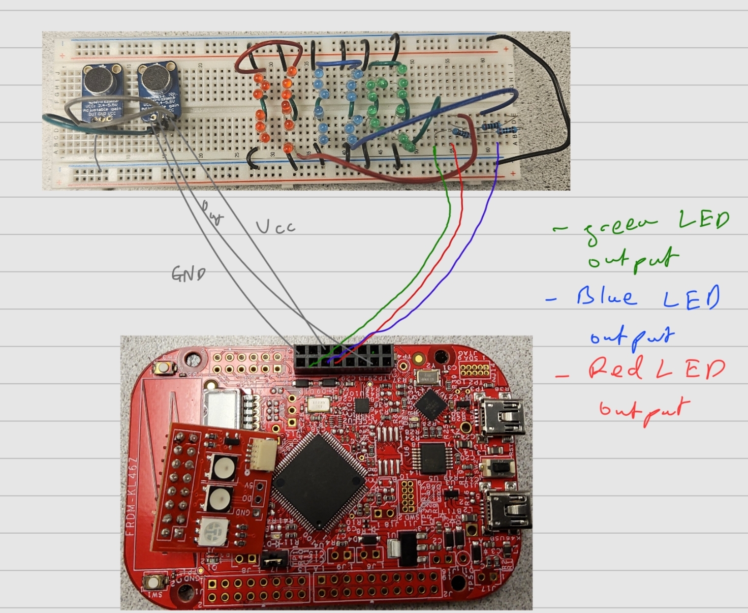
First going over the hardware of the mechanism, there weren’t too many extra parts that were needed besides the FRDM-KL46Z board. The main external components were two MAX4466 Electret Microphone Amplifiers and multiple different colored LED’s. As said earlier, the goal of this project was to use ADC to take in Audio frequencies and flash the corresponding LED/s with said frequencies. For the input side of the hardware, the mic Amps have three connections; one to GND, one to VCC (which has an input voltage of 2.4V to 5.5V) and one to Out. These pins were connected respectively to the GND pin, 5V out pin, and pte19 pins of the FRDM board. For the output side of the hardware, our goal was to have different LED’s light up based on which GPIO pin was set to high as an output. This meant we needed to wire multiple different LED’s to the FRDM board. This was done by connecting the GND from the board to the short ends of the LED’s and connecting the long positive ends of LED’s to resistors to control the current and connected to the other end of the resistors were the GPIO pins.
Next, going over the software that was used in the project, we mainly needed to the ADC.h library to convert the ADC values to frequency values and based on the frequency values we obtained, we would then set the specific GPIO pin as an output and HIGH, which would then turn on the corresponding LED.
Testing
In terms of testing we mainly used Test Driven Development(TDD) to implement the functionality of our project. The first thing we tested was configuring the LED’s to light up when outputting a high voltage from their respective pins. This was done by using some of the code from the LED.h files from the labs and using them in our main function. With this, we then had to set up the microphones and test whether the FRDM board could actually receive the frequency readings being transmitted using our code alongside the ADC library. For this part, we isolated the board to only be connected to a singular microphone and tested whether outputs were being read using the debugger. After we had tested both inputting frequencies and outputting LED’s to make them light up, we now had to test whether both of these parts could work simultaneously. This required us to test different resistor values and testing value ranges of frequencies from the mic to map to each LED.
Resources
The main resource that we used was the built in the ADC Library which was already given to us in our drivers. We also used the LED.H files from the previous labs and integrated those into our code.
Work Distribution
In terms of the distribution of work, most of the work was done together. Initial meetings were done over Zoom since they were more based on planning out our course of action. After we had a solid idea of how to implement the project, we would meet up usually in Phillips hall to work on the project together. Most of the hardware was assembled together along with the coding of the software but when it came to debugging software, some of it was done individually.
YouTube Demo Link
https://youtu.be/QwKmXCfSBM4