MZLed!
Introduction
A VU meter is a necessary tool in music production that displays the volume level of the signal passing through. This is important in preventing clipping, which is distortion of the audio sample due to a high input/output level. Clipping leads to unwanted crunching sounds and artifacts that if unintentionally applied, can dramatically lower the audio track’s sound quality. A digital VU meter’s display is green when the audio signal is within normal audio levels, yellow when near clipping levels, and red when clipping.
Overview
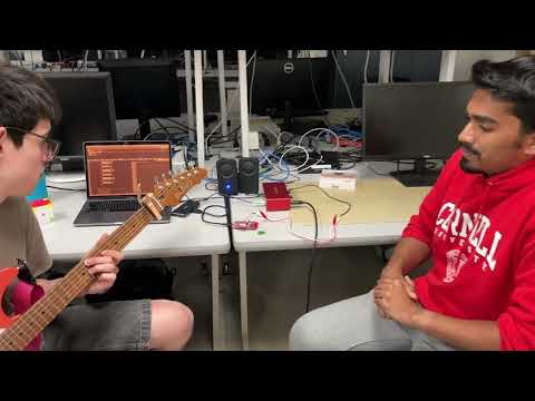
Our digital VU meter is displayed on the two LEDs that are on the attached board. We use the ADC on the board to get the audio signal, and then display the associated LED color with the amplitude of the signal.

The picture shows the different elements of our project including our input source, ADC (Analog to Digital circuit), FRDM-KL67 board, and LED output.
Video
Technical Approach
ADC setup/calibration:
We used the ADC code provided by Professor Napp named adc_example. The code goes through these steps:
First, we enable the clock to the ADC as a whole and set the the resolution of our readings to 10-bits (values range from 0 to 1023.)

Figure: ADC Initialization
Then we calibrate the ADC registers to acquire accurate readings. This involves performing hardware averaging, running a calibration routine, and applying calculated offset and gain correction values to ensure accurate analog-to-digital conversions. We decided to turn off hardware averaging later in order have more responsivness to changing input signals to the ADC.


Figure: ADC Calibration
Shown in the next section, there is a while loop in main() that continuously acquires the the ADC values and prints them out.
Here is a demo of this specific code working:
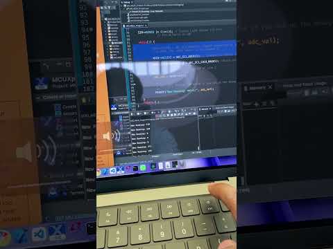
Here we are sending a signal from a tone generator directly to pin PTE20 and are reading the values from the the ADC in the debug console.
Translating the sound signal to light on the LEDs:

Figure: Global variables
Main(): This section of code is dedicated to the initialization of the board, LEDs, PIT timer, and interrupts. We are running the board at 15MHz and the PIT timer is firing every 750000 cycles.

Figure: Intializations
In our while loop, we get the conversion for the ADC value and set it to the global variable light_val. We had to change the channel of the ADCH from 3 (given in the example code) to 0 to get the correct channel to read from, as the 3rd channel is for the light sensor (but for this project, we are using the port E ADC).

Figure: ADC while loop in main
PIT IRQ Handler:
Our PIT IRQ Handler is where we use the light_value variable to illuminate our lights. Every 750,000 cycles, the LED’s color and brightness are updated with the ADC reading.
We have integer threshold values for the red and yellow values, where red is 150 and yellow is 100. When the ADC reading is larger than 150, then the LEDs will illuminate red. When the ADC readings are between 100 and 150, the LEDs illuminate yellow. If the ADC value is between 50 and 100, then the green LED is illuminated, Otherwise, the LEDs dim by a constant of 25 every time the PIT is fired until they either go to 0 or an ADC reading greater than 50 is read at the time of the IRQ handler being called. We used an array of the 32 bit rgb struct type grb32_t to set the red, green, and blue values and illuminate them using the set_leds() function. We apply these four cases in an if-else statement.

Figure: Logic for red LED.

Figure: Else case - Fading LEDS decrementing by 25
Testing and Debugging
Talk about your testing approach or subtle bugs you made/found.
We tested our project in incremental steps going from testing the first part which is the adc to testing if the signal translating is working.
The debugger console can only display values so fast, so it was difficult to see the values from the ADC at the exact instant they are taken in. This made it difficult to test responsivness. That being said, we had to make sure the LED code was working to test latency issues between the ADC and the LEDs. We had to adjust our PIT timer numerous times before we hit a sweet spot in responsiveness.
Another difficulty while testing was unexpected ADC values when no signal was being sent. In order to mitigate this issue, we had another threshold value to ensure the LED’s did not turn on unless signals pass this certain threshold.
Our testing and debugging strategy heaily relied on playing different amplitude and pitched sounds. For example, when conducting testing with the guitar, we observed how different playing styles affected the audio reactivity of the light. The biggest challenge for us during the debug period was getting the lights to illuminate but also disappear within an appropriate time frame such that pulsating rhythms could be visualized. This was where we constructed the else branch for our irq handler. Without this function, the LEDs would shut off immediately without any residual effect. During this time, we also adjusted the red and yellow thresholds as well as the decrement amount.
Team Work
Zarif mostly worked on the circuitry and ADC testing involved in our embedded system, Matt mostly worked on the functionality of the code, and Mohammad mostly worked ADC pin setup and the website. That being said, we all helped and checked each other’s work and understood the different parts that went into our project.
Outside Resources
Our code was inspired by a lot of the labs we did previosuly in this course but we didnt use any sources that are outside of this class.