ECE3140 / CS3420 Final Project Page
GAMEBOARD w. GuessMorse & RxnTime

Introduction
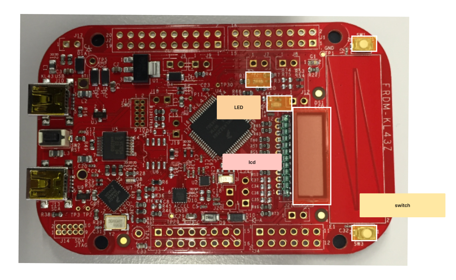
We set out to create a reaction time game and mini Morse Code game using just the FRDM-KL46Z board. The reaction time game is essentially measuring how fast the user responds to the green LED. For the Morse Code game, the board creates a random Morse Code that represents one of the digits 0 to 9 using the LEDs. The user has 3 tries to guess the Morse Code to win this game. Ultimately, we wanted to create something fun that incorporated what we learned in class but was also something that our friends on campus could play as well.
Game Overview
Our board has 2 games: reaction game and morse guessing game. Users play the reaction game first then the morse code game.
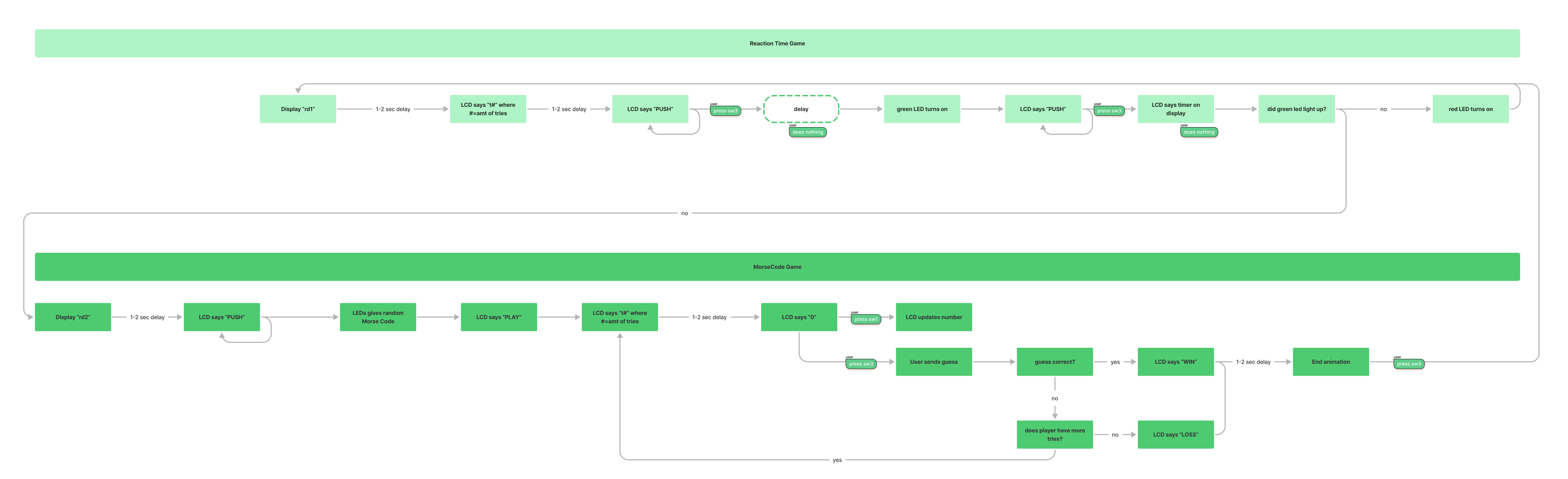
The flow of the game goes like this:
- In the beginning of the game the LCD display will show rd1 to indicate that you are currently playing the Reaction Time Game.
- t1 will show up after 1~2 second to indicate that you are on the first try of the RT game.
- Then after 1~2 second PUSH will be shown on the LCD screen which will prompt you to push SW3. It will stay this way until you PUSH SW3.
- Then after some time the green LED will turn on and the PUSH on LCD will show up and then you will need to push the SW3 button as soon as you see the green LED. The green LED and the PUSH on LCD will remain until you push SW3. The time that you took to push the button will be shown for 1~2 seconds on the LCD display. The first digit represents the ten of a second, the second digit represents one of a second, the third digit represents the tenth of a second and the fourth digit represents the hundredth of a second.
- If you push the SW3 button before the green LED shows up then the red LED will flash and you will have to repeat the Reaction Time Game. The try that you will be on will once again show.
- Then you will be on to the next game which is the Morse Code game. The LCD display will indicate this by showing rd2 for 1~2 second.
- Then the LCD will display PUSH on the LCD display until you press the SW3. After you do, the Morse Code will show. The dashes represent the green LED and the dots represent the red LED.
- Then the word PLAY will show in the LCD display for 1-2 seconds and then on the LCD display it will show the try you are on and the number you are guessing. You can use SW1 to increment your guess and SW3 to input your guess. You will have 3 tries in total to guess the Morse Code. If you fail to guess the Morse Code then the word LOSS will display in the LCD display for 1-2 seconds and if you succeed in guessing the Morse Code then the word WIN will display for 1-2 seconds.
- Then at the end, there will be the END display animation. You can hit the RESET button to restart the whole game.
System Overview
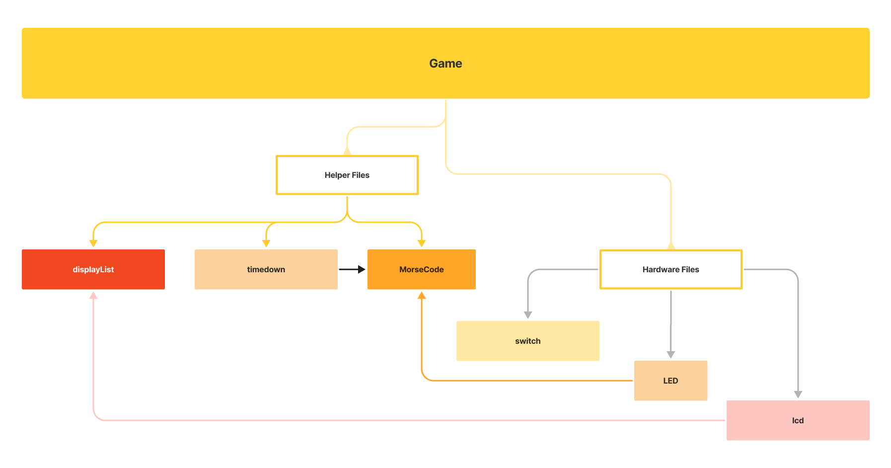
Our game is divided into multiple files in source folder: LED, MorseCode, displayList, game, lcd, switch, timedown.
The LED files initializes the red and green LEDs and creates functions of red and green LED that will be used in game. For example, the LED signals what morse digit using blinks with long and short delays in MorseCode.
The MorseCode files store the functions GenerateMorse() and their helper functions like shortdelay(), longdelay(), dash(), and dot(). These are functions that are used to convert integers to morse.
The lcd file sets up the LCD display board for use. The LCD will prompt users what to do, tell users what stage of the game or what try the user is at as well as tell the user how fast the user reacted to the green LED. The displayList file has a list of functions that use the lcd file that help display words such as LOSS, WIN, PLAY, STOP and our ending animations using functions from lcd.
The switch file controls initialization of SW1 and SW3. SW1 is primarily used for input and SW3 as a button (that triggers) the next stage. It also has global variables like SW1pressed and SW3pressed to keep track of which button is pressed and use this information to faciliate the games. We depended on PORTC_PORTD_IRQHandler to detect which switches were pressed. We will be able to get the global variable for other files using getter functions as well as using reset functions when we have to reset the switch global variables as we have to transition to a different stage of the game.
The function timer_countdown() in the Timedown file acts as the random number generator. The function timer_countdown_show() is used for displaying how fast the user reacted in the ReactionTime game. Surprisingly, rand() and srand() do not work with embedded systems because these are pseudo code; therefore, timer_countdown function was made which is a running timer that is dependent on user input (user pressing SW3). When the function is called, the timer runs and stops when the user presses SW3. When user presses SW3, the function returns the hundredth second of the timer and uses this integer as the randomly generated integer. In addition, Timedown files had additional functions like sec_delay(), tenth_delay() and hundredth_delay() that we used in our game file to create delays.
Our Game file is the home of the game logic and uses all the aforementioned files as building blocks. We kept the file clean and readable with a modular project design. Each file focuses on doing one thing well and we call everything in the game.c.
Project Video Demo
If the link above doesn't work try this link
Detailed Technical Description
In the system overview, we reference our modular project design. As we built each module, we used test drive development. This programming style allowed us to catch our issues with our game, especially with the random and switch classes. We wanted each file to do their tasks well before we tackled putting them together for the game file!
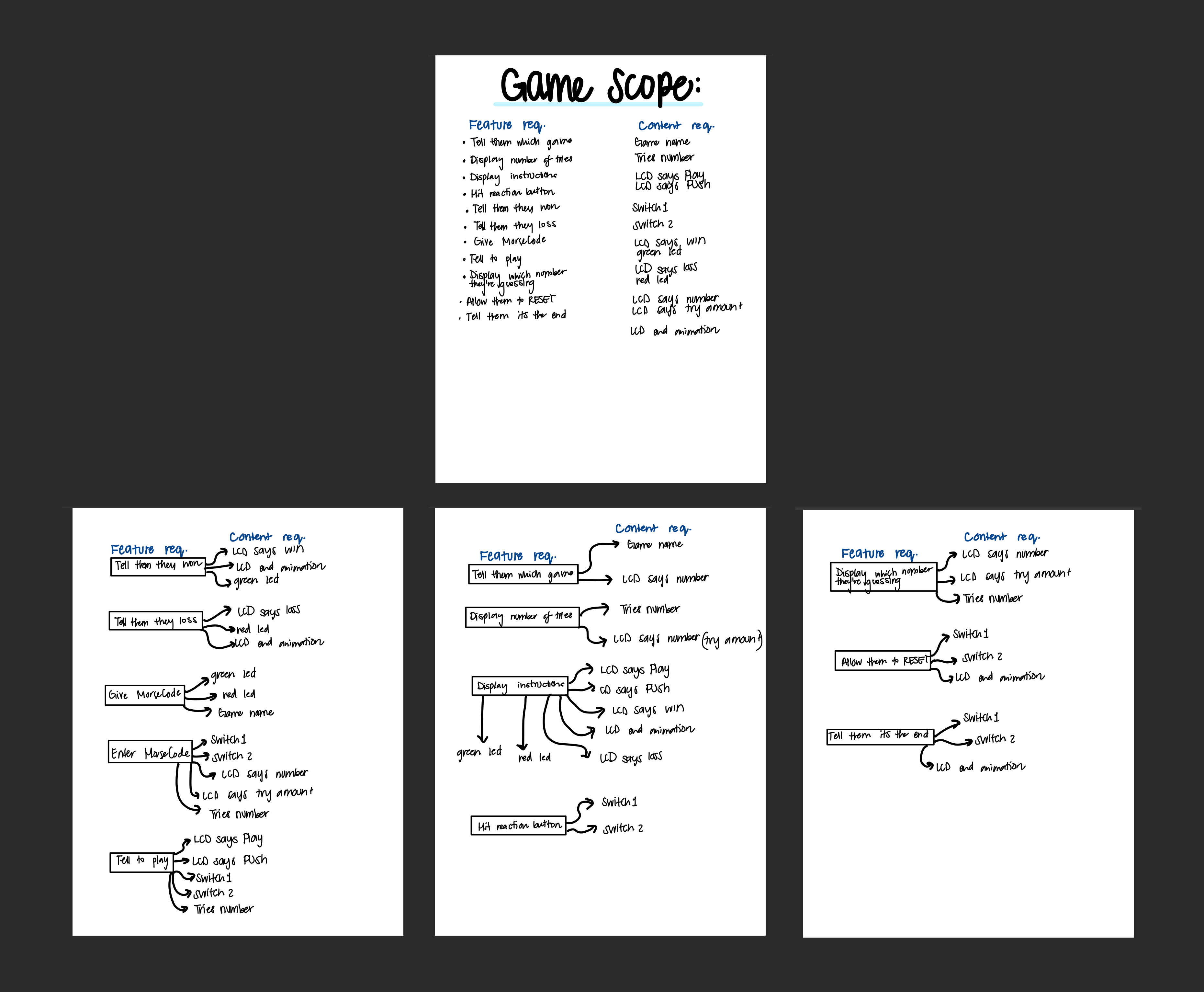
First, Junwoo broke the game into components to decide which parts we needed to implement. Here we decided, we’d test the switch, LCD and random function separately to ensure they work before we started testing the game.
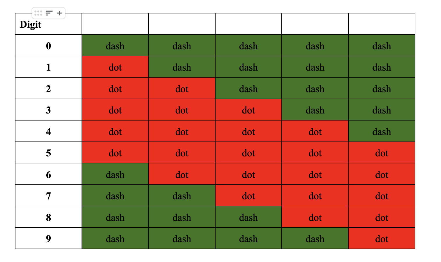
Then, Junwoo coded an optimal MorseCode function following the design from our first lab unit as shown in the picture above. Junwoo wrote an optimal function by not having morse cases for each digit but rather have two for loops for two different cases, one loop in which the dots go first then dashes and one loop in which the dashes go first then dots. Each loop would have 5 dashes and dots combined and different amount of dashes and dots based on the given digit. In order to test our MorseCode function, Junwoo physically inserted digits 0~9 and saw if they gave the dashes and dots that each digits displayed.
Then, we figured out how to use LCDs from the LCD library demo. Since we had multiple games, Junwoo thought of putting all the display words (like Play, Win, and Loss) and ending animations in one file for game.c. The functions in display turn on the segments for each letter for our display words. Junwoo was able to check each of the words displayed correctly as they were implemented.
A majority of the project time was spent trying to code a random number generator for an embedded system. srand() and rand() didn’t work in testing, so Tise tried a seed based random number generator. But that wasn’t the full solution because you still needed to generate a different number for the seed and stream or else we’d get 8 each time. So, Junwoo coded a time based random number generator in timedown.c. We’d later add the delay functions for game.c in timedown as well since timedown functioned as our games clock.
Another struggle was the switch and pin connections. We originally could not get both switches to work at the same time. Then, we learned both switches could share a port connection but different pins and we can differentiate between which pin is called using ISFR in PORTC.
Once the components of the game were tested and ready, we started calling them in the game file. At this point, Junwoo realized we needed to add delays for the game to flow better. Tise designed the reaction time game flow since we wanted to add a second game based on our feedback in the github readme and per TA’s advice. With the second game, we re-modularized the code and Junwoo added a displayList file so both games could access the display words for game play.
Testing
Due to the fact that our project was composed of series of games, much of the testing came from us interacting with the FRDM46Z Board rather than building test cases. We would first break down the essential components that we needed for the game as explained in the section above. Those were the switches, LEDs, LCD display, Morse Code, some sort of random int generator function. Since we were given the LEDs library files, we assumed it is correct in terms of functionality. Then we would use the LED to test the switches. For example, when we pressed SW1, the green LED will turn on and when we pressed SW3, the red LED will turn on. This is how we essentially tested that our switch was working correctly and separately (one switch is not affecting the other switch). Then we used the switch functionality when building random int generator and the LCD functionality to display the functionality of the random int generator working. In essence, this is what we did for the whole project, we started out with the most basic part of what we needed and once we have tested its correct functionality we would use it to test build something more complex and even use it as a medium for testing. This is a similar concept as to test driven development and this is how we efficiently built the reaction time game and the morse code game.
Connection to class and Reflection
What we used from class was the Morse Code implementation but it is more efficient as well as ideas from Lab2: GPIO & Interrupts. We also spent a lot more time looking at the manual in order to use the functionalities of the board that we didn’t previously use before such as the switch. We learned that the manual actually provides many hidden aspects of the board and we just need to take our time to read the manual to unlock the board’s true potential :)
Citations
- https://community.nxp.com/t5/Kinetis-Design-Studio/Interrupt-in-kl46Z/td-p/457768 | This website helped us realize that even though SW1 and SW3 are in the same PORTC, we can distinguish them using the PORTC_ISFR register.
- We also used the KL46 Sub-Family Reference Manual to set up the SW1 and SW3.
- The LCD library was provided to us by Aaron Wilhelm.
- The LED library was used from the previous labs that we have done.
- We use the basic outline for 0~9 digit morse code from lab 1 provided to us by our Professor Napps.
- We also did a heavy modification of the SW demo file that was provided to us via canvas
Work Distribution
Junwoo and Tise first brainstormed ideas for the final project but they both agreed they wanted to do a game or something with a graphics component. Junwoo suggested a morecode guessing game and started coding the optimal Morse Code function. Tise asked on ed for LCD and switch files. Then, Junwoo figured out how to use the LCDs and wrote display functions for the game. Tise and Junwoo both worked on trying to create a random generator function for the game: Junwoo came up with the time based solution. Tise and Junwoo also went to OH and used ed to write the switch file. Both Tise and Junwoo did code cleaning and contributed to the modular design. Tise designed the reaction time game that Junwoo implemented. Junwoo re-modularized the code with the new game. Both Tise and Junwoo co-wrote the Progress update and final website writuep. Junwoo recorded the gameplay demo for the video. Tise wrote and edited the final pitch video. Tise cleaned up the website and drew/designed all the graphics in Figma.