 Table of Contents
- Introduction
- System Overview
- Project Video Demonstration
- Detailed Technical Description
- Testing and Validation
- Learnings and Class Material Used
- Sources
- Work Distribution
Introduction
While the advent of cheap window mounted air conditioning units allowed much of the US to be able to cool their houses, the most affordable units do not posses any temperature regulating processes. These units almost always rely on the user to constantly modify the settings in order to achieve the perfect temperature. The system described below cheaply resolves this problem with. In escence, this system turns a dumb window air conditioning unit smart by adding room temperature regulation.
System Overview
The goal of this system is to allow a user to set a desired room temperature, and then have the board measure the ambient room temperature and adjust the knob on the window unit accordingly using a servo motor.
This system consists of 4 main parts with 2 of them being external devices connected as outlined in the system diagram below.
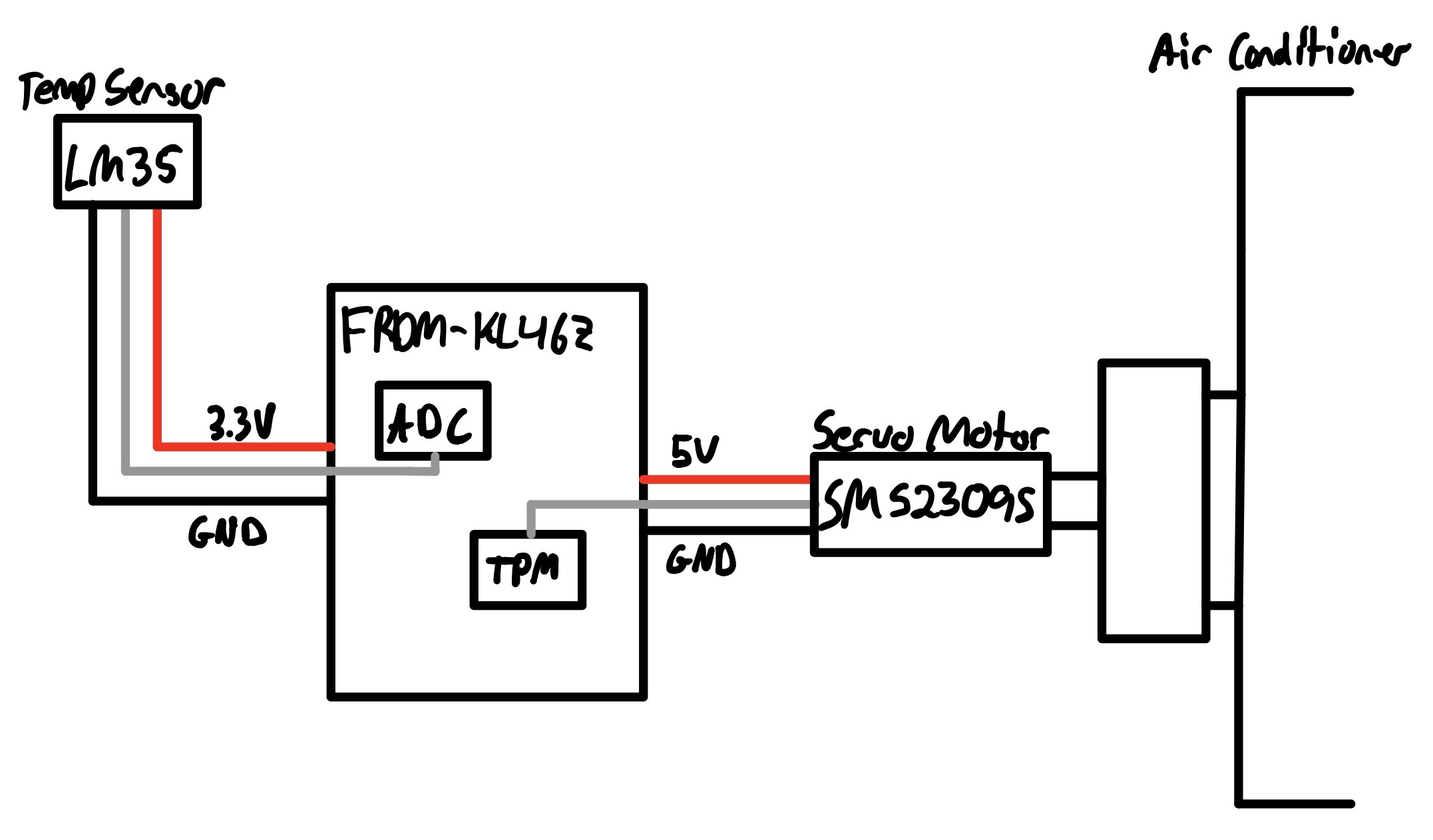
1) Measurement. The microcontroller's ADC is used to read a small temperature sensor that is placed several feet from the actual window unit. This is to allow for accurate ambient temperature readings that are not affected by the cool air or the window unit's heat exchanger. This sensor is read once every minute to ensure constant adjustments are not made, and the room has a chance to cool or heat before the next reading is taken. Then, if the room is too cold, the temperature is turned up, and if the room is too hot, the temperature is turned down.
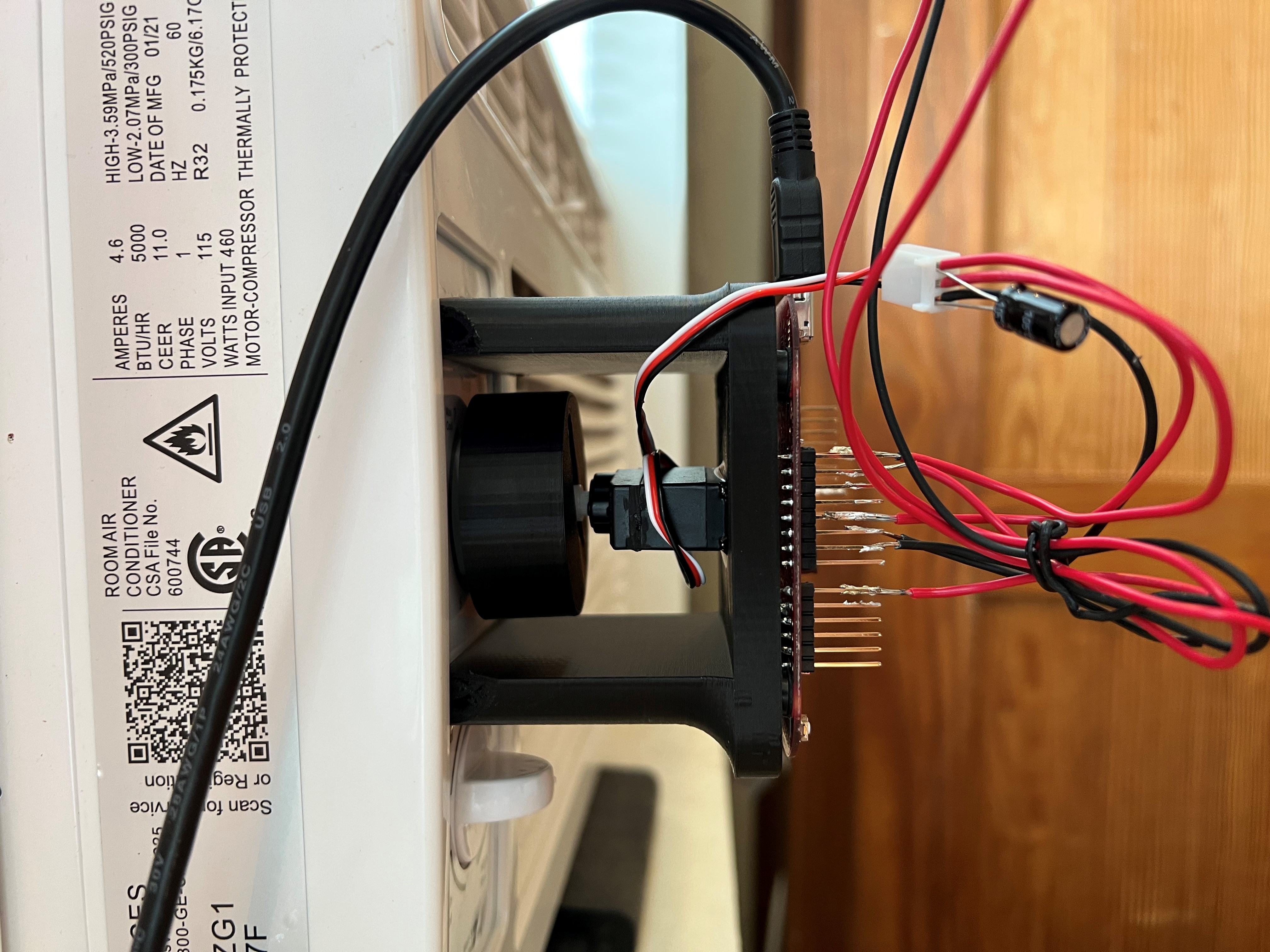
2) Computer-Air Conditioner interaction. This is done by a servo motor (Model SM S2309S) mounted via a 3D printed bracket to the front of the AC unit. The axle is then connected to the temperature adjustment knob with a 3D printed adapter. This then allows the board to control the AC unit's controls.
3) Human-Computer interaction. The board comes standard with two push buttons on the bottom of the board. These are used to set the desired temperature. The left button decreases the set temperature, and the right button increases it.
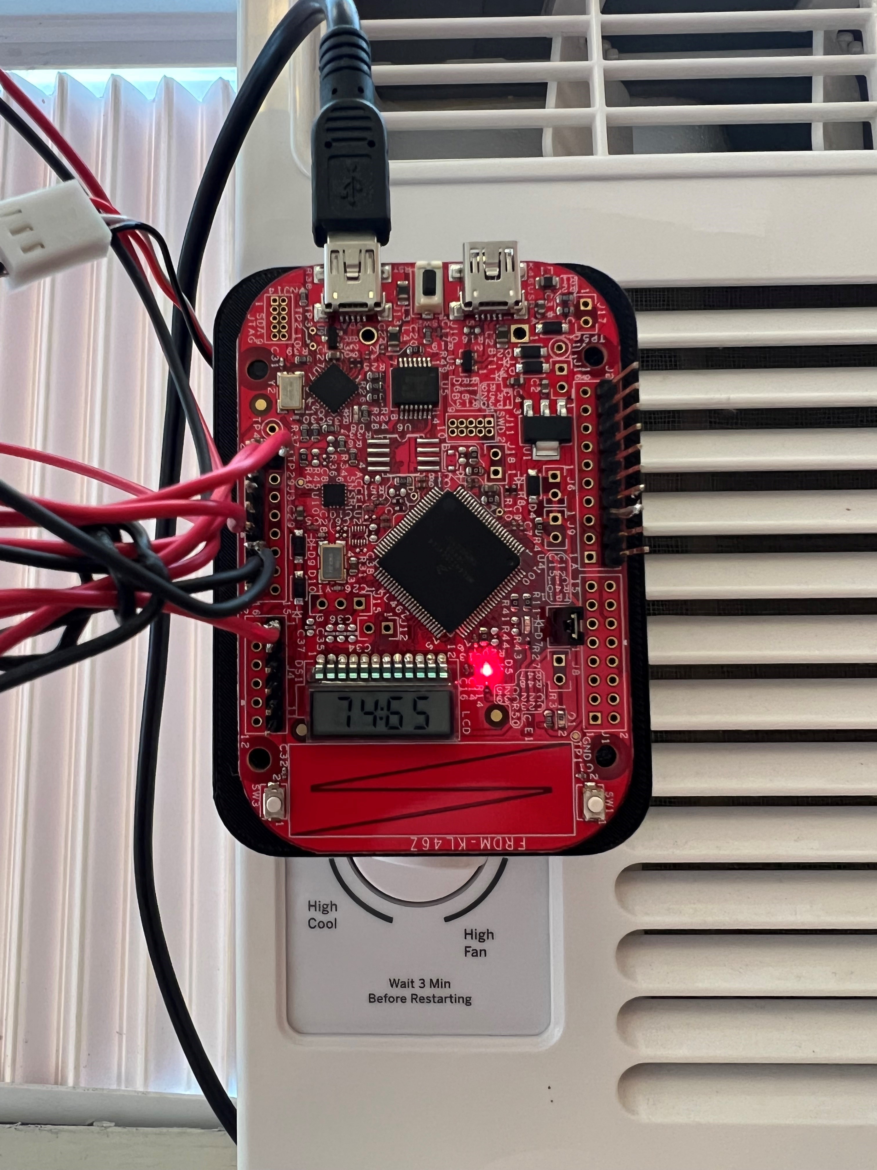
4) Computer-Human interaction. In order for the user to know the status of both the set temperature that is controlled by the buttons and the measured temperature, the on board LCD screen displays both. The LCD screen displays the measured temperature (0-99 Degrees Fahrenheit) with the left two digits and the set temperature (0-99 Degrees Fahrenheit) with the right two digits. For readability, the center colon is also illuminated. In order for the user to determine the system status at a glance the green and red onboard LEDs are used to display whether or not the room is at the correct temperature. If the room is within a degree of the desired temperature, the green LED shines, if the room is not, the red LED shines.
Project Video Demonstration
Note about the demonstration video: Seen below is a small video demonstration of the full system. The initialization sequence of the system shows the full range of motion set for the servo motor. Then you will see me adjust the set temperature (the right two digits of the LCD display) as the 5000-point running average builds up to the room temperature. In that progression you will be able to barely hear one of the 10 degree adjustments that the servo motor makes. You will also see how the LEDs function. The difficult part about a demonstration video of this style is the length required to show the full effectiveness of the system. The system does indeed keep the room roughly at a temperature, but it does it over 15-30 minutes.
For another viewing option: https://youtu.be/lq29TgNyEmo
Detailed Technical Description
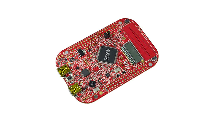
The microcontroller used for this project is the FRDM-KL46Z from NXP (seen below).
1) Measurement
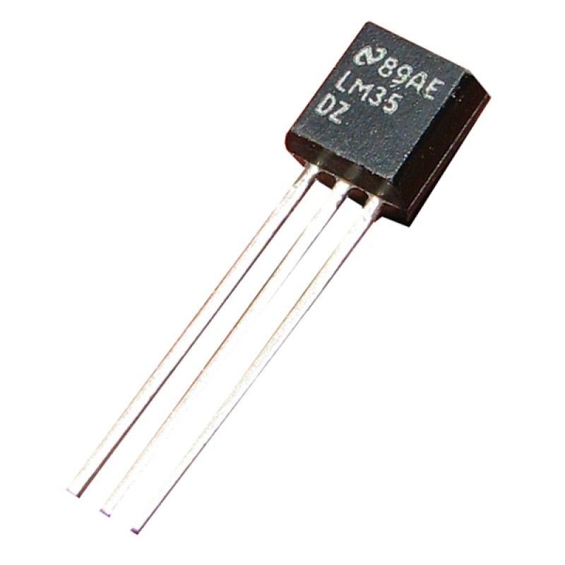
The temperature sensor used is model LM35 (seen below). This sensor is an integrated circuit analog temperature sensor that outputs a voltage that linearly increases from the reference low to the reference high as the temperature increases. The sensor can range from -55 to 150 degrees Celsius. This sensor is optimal for this project as it requires no calibration and will consistently output the same relative voltage even when power is cycled.
Given the analog nature of the sensor output, the on-board Analog to Digital Converter (ADC) is required to measure the temperature. On this board the ADC must be both initialized and calibrated once the clock has been enabled and an input pin enabled. The ADC has a built-in calibration function, but it must be run as many times as needed until a successful completion. Once it is complete, 10 calibration offset registers are set and must be used to calculate the plus and minus gain offsets.
Once the calibration is complete, the readings are initialized by writing to the SC1A channel of the ADC and the result can be read once the measurement is complete. The measurement completed flag is reset by reading the result register. This reading then must be converted into a temperature. This is done via a linear mapping of the 0-3.3V onto the -55-150 degrees C. First the 3.3V-0V range is divided into segments by dividing 3300mV by 16bits. This results in a linear mapping between mV per increase in ADC reading. That mapping is then multiplied by the ADC reading to convert the ADC reading into mV. Then the LM35 has a formula for calculating degrees C given a mV reading: (mV - 500) / 10 = Degrees C. The final output is in Fahrenheit so a simple conversion of (Degrees C) * 1.8 + 32 = (Degrees F) is needed.
To combat noise in the ADC, a 5000-point running average is then applied to the temperature reading. This is done using a 5000-point array. This results in a very accurate temperature reading.
2) Computer-Air Conditioner interaction
In order for the board to adjust the air conditioner's settings, a physical interface is needed. This is done via a 3D printed mounting system. A simple plate was printed to hold the board and servo motor in front of the air conditioner. The board press fits into the printed holes on the front of the plate and the servo motor was glued onto the back of the plate. The motor is interfaced to the "Cooling Level" knob via a 3D printed adapter.
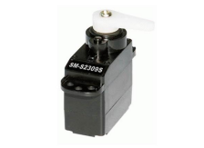
Servo motors are driven by a modulated pulse system. The angle of rotation is determined by changing the time the pulse spends on high vs low. This specific servo motor (Model SM S2309S) uses 20ms pulses with a 1-2ms high time (seen below). A 1ms high time corresponds to a 0-degree rotation, and a 2ms high time corresponds to a 180-degree rotation. the other angles are achieved by linearly mapping 0-180 degrees onto 1-2ms. To generate a pulse width modified signal, the Timer / Pulse Width Module (TPM) must be used. This module must be set in Edge-Aligned PWM mode to power this servo motor. The period and pulse width can then be chosen given the clock prescaler. To change the angle of the servo motor rotation, a new pulse width is written into the corresponding channel register.
In order to only adjust the temperature every so often, the Periodic Interrupt Timer (PIT) module is used to generate an interrupt every one minute. This interrupt triggers a flag that signifies a servo adjustment can be made. The adjustments are made by adding or subtracting 10 degrees from the current angle. This allows the room temperature to have a minute to equalize before the next adjustment is made. The servo is set so that 0 degrees is the coolest and 180 degrees is the least cool.
3) Human-Computer Interaction
For the user to be able to input a desired set temperature into the system, the two on-board buttons are used. The buttons are configured to trigger an interrupt on the rising edge due to the choice to use a pull up resistor. Then, depending on which button triggered the interrupt, the set temperature is either increased or decreased. Since this task is so short, it can be done in the interrupt service routine without any disruption to functionality.
4) Computer-Human interaction
The ability for the user to know the set temperature and current ambient temperature is critical to make this system enjoyable. This is accomplished through the on-board LCD screen. This display consists of 4 7-segment displays and a colon. This display has two refresh triggers because the display, if refreshed with every measurement, becomes almost unreadable due to the frequency of new temperature measurements. So, to combat this, another channel of the PIT is used to generate interrupts every 1 second. The interrupt service routine distinguishes between the two PIT channels and sets a corresponding flag. This flag is then used in the main loop to trigger a display refresh. This allows the temperature measurement to be easily readable despite the speed of new measurements. The second display refresh trigger is the interrupts generated by a button press. This allows the display to both be extremely responsive to the user, and not have a refresh frequency that becomes overwhelming.
The main limitation of the LCD display is its lack of viewing angles. To combat this, the on-board LEDs are used to indicate the status of the measured temperature relative to the desired temperature. If the temperature is more than 1 degree different from the desired temperature, then the red LED is turned on. Otherwise, the green LED is turned on.
Testing and Validation
Testing this project involved testing each part separately, and then testing all parts together.
1) Temperature Sensor
Ensuring proper functionality of the temperature sensors was paramount to the success of this project. This part also proved to be the most difficult to implement, as the ADC has a complicated initialization protocol. Initially once the sensor was outputting a reading, the LCD display was used to display the raw reading. Then the sensor was warmed using the body and cooled by blowing on it, and the value was ensured to lower when cooled and increase when warmed. Then, the raw reading was converted to a temperature, as outlined above, and was displayed on the LCD screen. Since the measurements were taken so quickly, the display was occasionally difficult to read in both tests, but the trends could easily be seen. Once functionality was shown to be preserved with the rough temperature scale, accuracy was tested. This was done by placing the sensor against and ice cube and then clenched in the palm of a hand. These two temperatures are known to be 32- and 98-degrees F respectively. The sensor was slightly off from these values, so a multimeter was used to probe the voltage difference between the sensor output and ground. This was done at the sensor itself and at the connection to the board. This showed that there was a voltage drop over the wire. This was then accounted for by modifying the conversion numbers until accurate readings were seen.
2) Servo Motor
Once the servo motor was able to move using the TPM, testing it was straight forward, but revealed issues. Initially, when the motor driving method was given a 0-degree input and a 180 degree input, the motor would only rotate a few degrees. This was difficult to diagnose as the TPM was being modulated to the servo motor's specification sheet's preferences, and I had no access to an oscilloscope. This resulted in trying many different values for the pulse width to see how the motor responded. I then linearly mapped the values I found to work for 0 and 180 degrees onto the specification sheet's formula. This resulted in a perfectly functioning servo motor, but when the rest of the functionality was enabled, all of the values became inaccurate again. I believe this is due to the 5V source powering the motor being from the USB port. Thus, when more modules were used, the current supplied was further divided which resulted in less movement from the servo motor. Once again, this resulted in me having to remap the correct pulse timings to the desired rotations. Once that was complete, full functionality was achieved.
3) Button Inputs, LCD Display, and LEDs
Testing the button inputs was straight forward. This was done by displaying the set temperature on the LCD screen and pressing the buttons in all sorts of speeds and orders. Then, I pressed the buttons until the set temperature was at 99 to ensure it could not go any higher, and I also ensured that the set temperature could not go lower than 0 degrees. This testing of the LCD was also done for the temperature reading by faking the measured temperature value and ensuring it never goes below 0 or higher than 99. The LEDs were tested by changing the set temperature to an arbitrary number, and then faking the measured temperature for 0-99 degrees.
4) Complete System Testing
Once the whole system was setup, functionality was tested by setting the temperature to 65, placing the temperature sensor on ice, and watching the servo motor over the course of 15 minutes. This should result in the cooling being turned all the way down, and it did. A similar test was done to ensure maximum cooling by placing the sensor above a mug of boiling water and setting the desired temperature to a low value.
Learnings and Class Material Used
In this project I used interrupts, the PIT, the TPM, GPIO ports, the LEDs, and the LCD. I learned a lot from this project. The main takeaway is the ability to read chip reference material and use different modules on the board. Some of the modules take more registers to enable than others, some require calibration, some require different clocks, and some have to be enabled in many places. This allowed me to get a much more holistic view of the board and appreciate its potential. The ADC was the most difficult part of the project due to the number of registers needed to achieve functionality.
Sources
In this project I used the FRDM-KL46Z reference booklet and prior class knowledge. I recieved help from one TA at office hours (you can see what code I was helped with in the source file). I also used the datasheets for the motor, temperature sensor, and FRDM-KL46Z board.
- FRDM-KL46Z Image Source: https://www.nxp.com/design/development-boards/freedom-development-boards/mcu-boards/freedom-development-platform-for-kinetis-kl3x-and-kl4x-mcus:FRDM-KL46Z
- LM35 Image Source: https://potentiallabs.com/cart/lm35-temp-sensor-india
- SM S2309S Image Source: https://descargas.cetronic.es/microservo.pdf
I completed this project alone.