Intelligent-Physical-Systems
Project maintained by jim59 Hosted on GitHub Pages — Theme by mattgraham
Lab 3
For this lab we were able to build and add an amplifier microphone circuit on the main breadboard, test the circuit with MATLAB and Arduino, & also install an override button.
- The amplifier microphone circuit will be used by the robot to detect a specific trigger frequency on a played melody that will signify the robot to start navigating around the maze.
- The override button is a pushbutton that will be used a backup option to signify the robot to start navigating in case the robot does not start navigating when the trigger frequency is played.
Accomplishment: BotMobile can now detect specific frequencies using the installed amplifier microphone
Phase I
For the first phase of this lab, we used LTSpice, a circuit simulation program, which allows you to draft, probe, and analyze the performance of the circuit design, to simulate lowpass, highpass, and bandpass passive filters for the amplifier microphone circuit.
After running the LTSpice simulation, we visualized a frequency response of the filter.
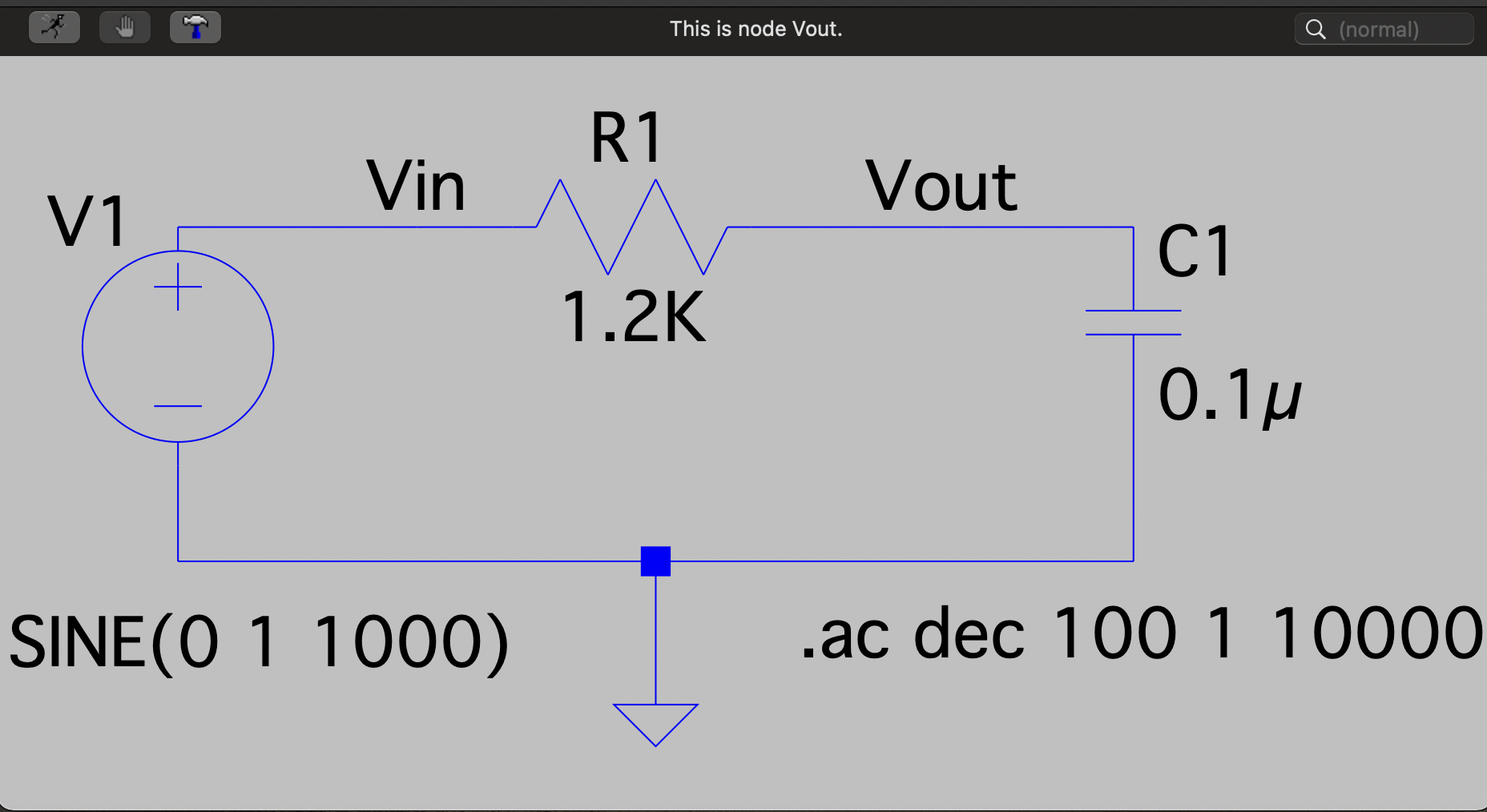
- We simulated the low-pass filter using a Resistor of 1.2k Ohms and a Capacitor of 0.1 microFarads.
LTspice low-pass RC circuit
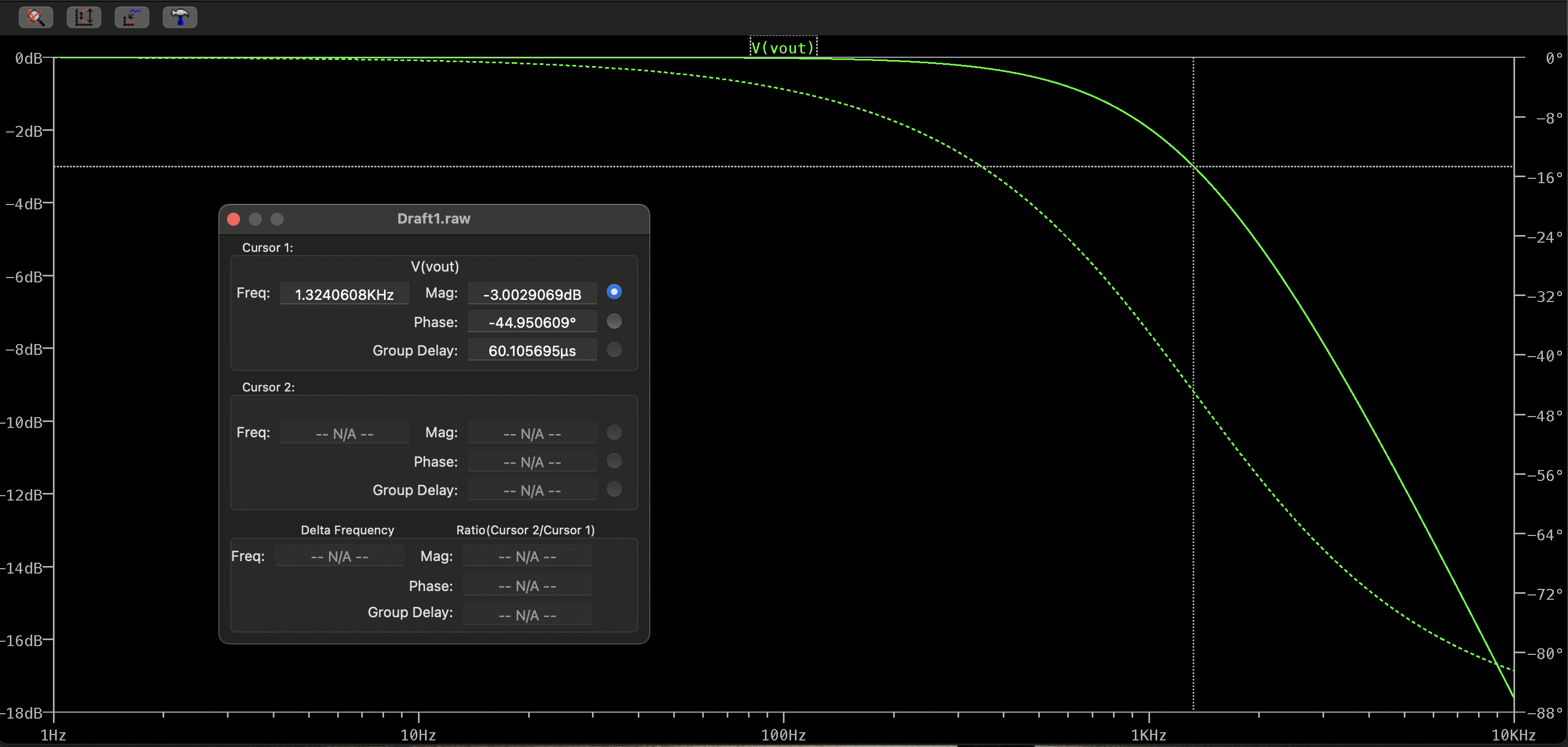
The frequency response graph for the frequency from 1Hz to 10kHz for the low-pass filter:
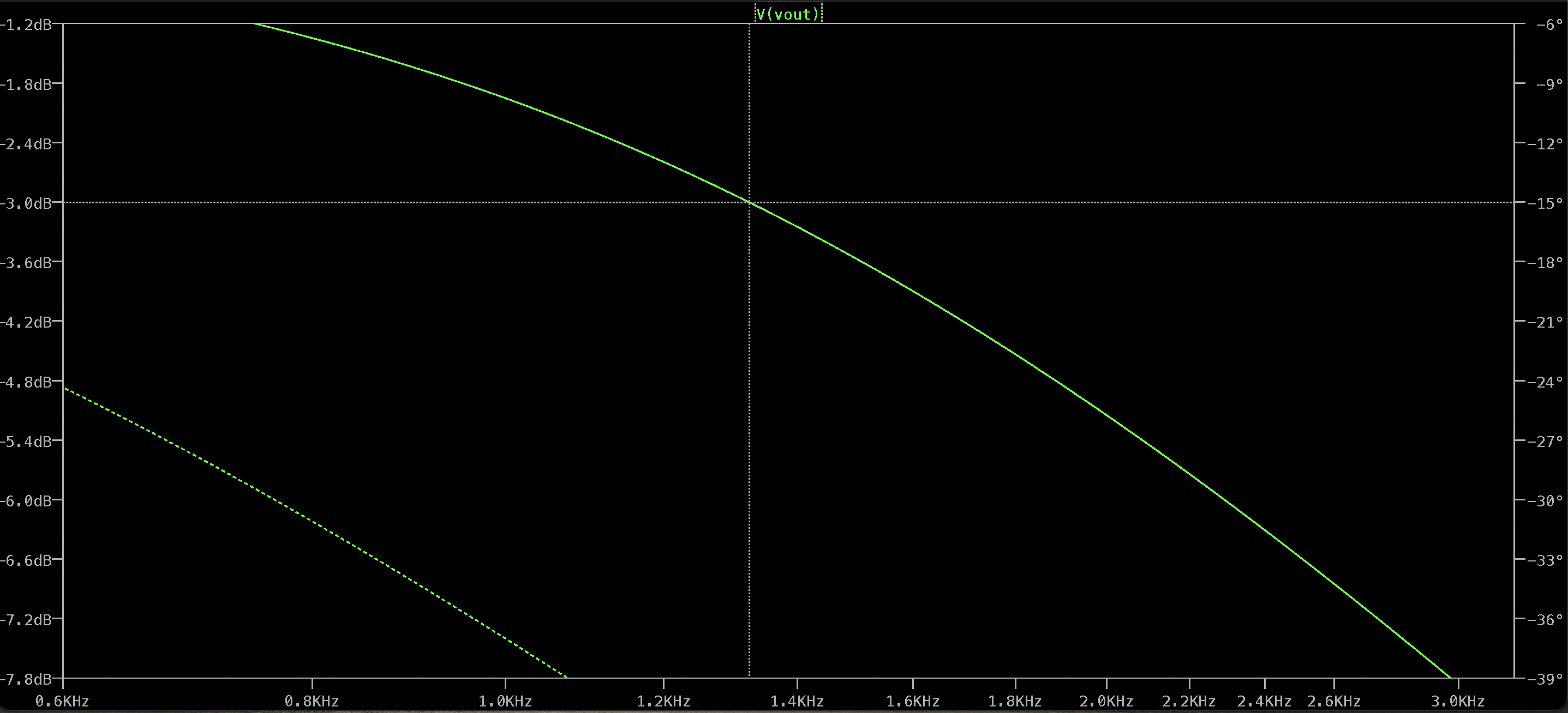
Zoomed-in graph around the curve where the cutoff frequency is located showing a cutoff frequency of around 1.3kHz:
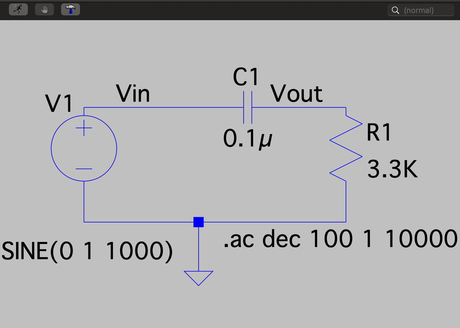
- We then simulated the high-pass filter using elements of the same values: a Resistor of 1.2k Ohms and a Capacitor of 0.1 microFarads.
LTspice high-pass RC circuit
The frequency response graph for the frequency from 1Hz to 10kHz for the low pass filter:
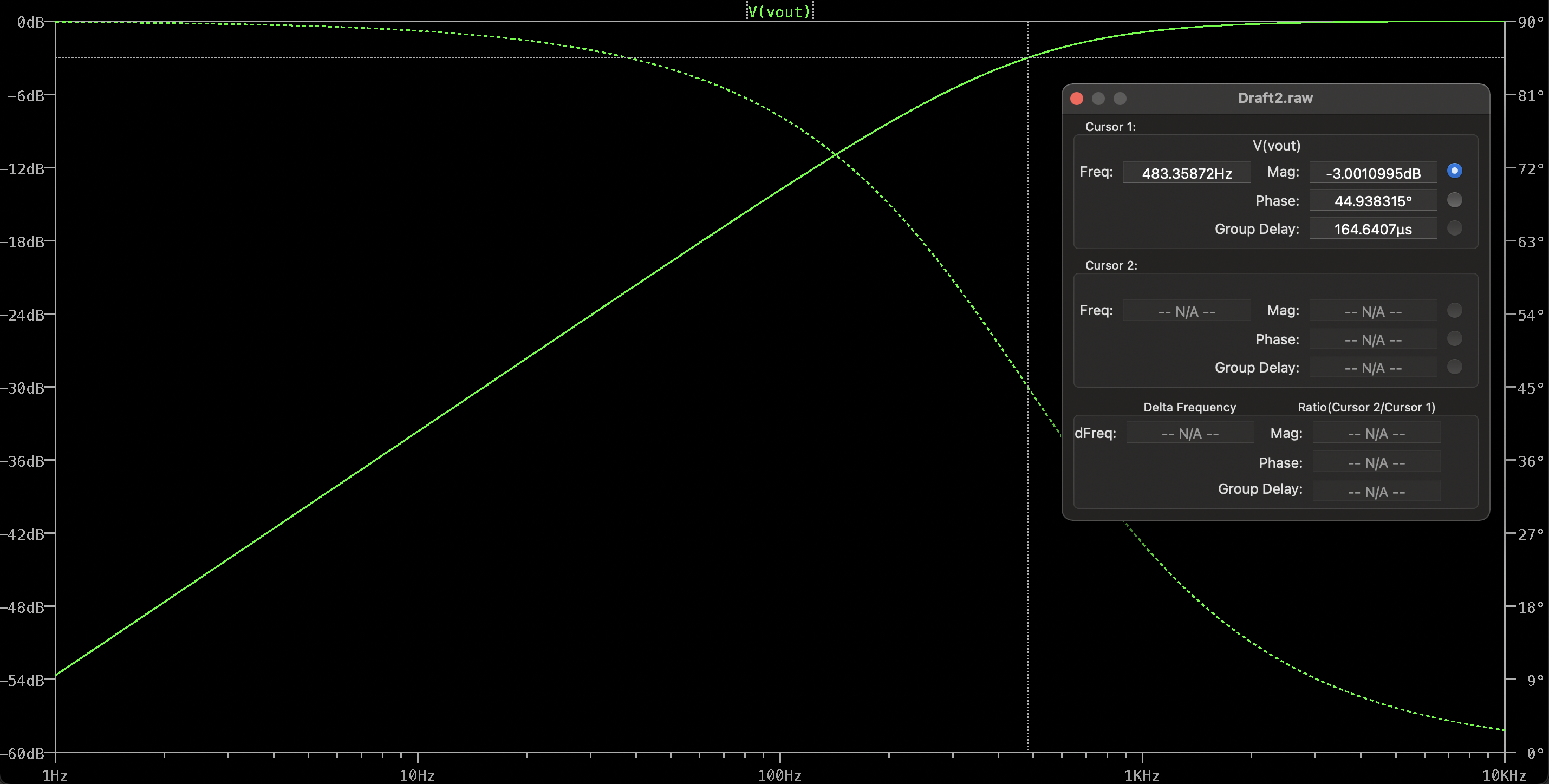
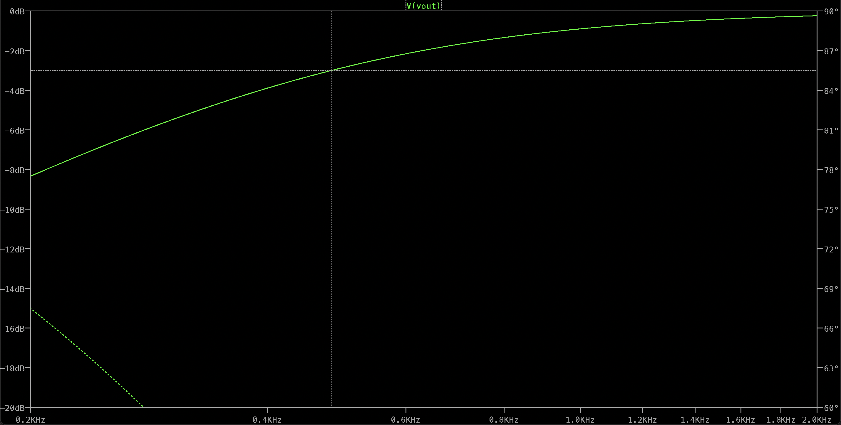
Zoomed-in graph around the curve where the cutoff frequency is located showing a cutoff frequency of around 483Hz:
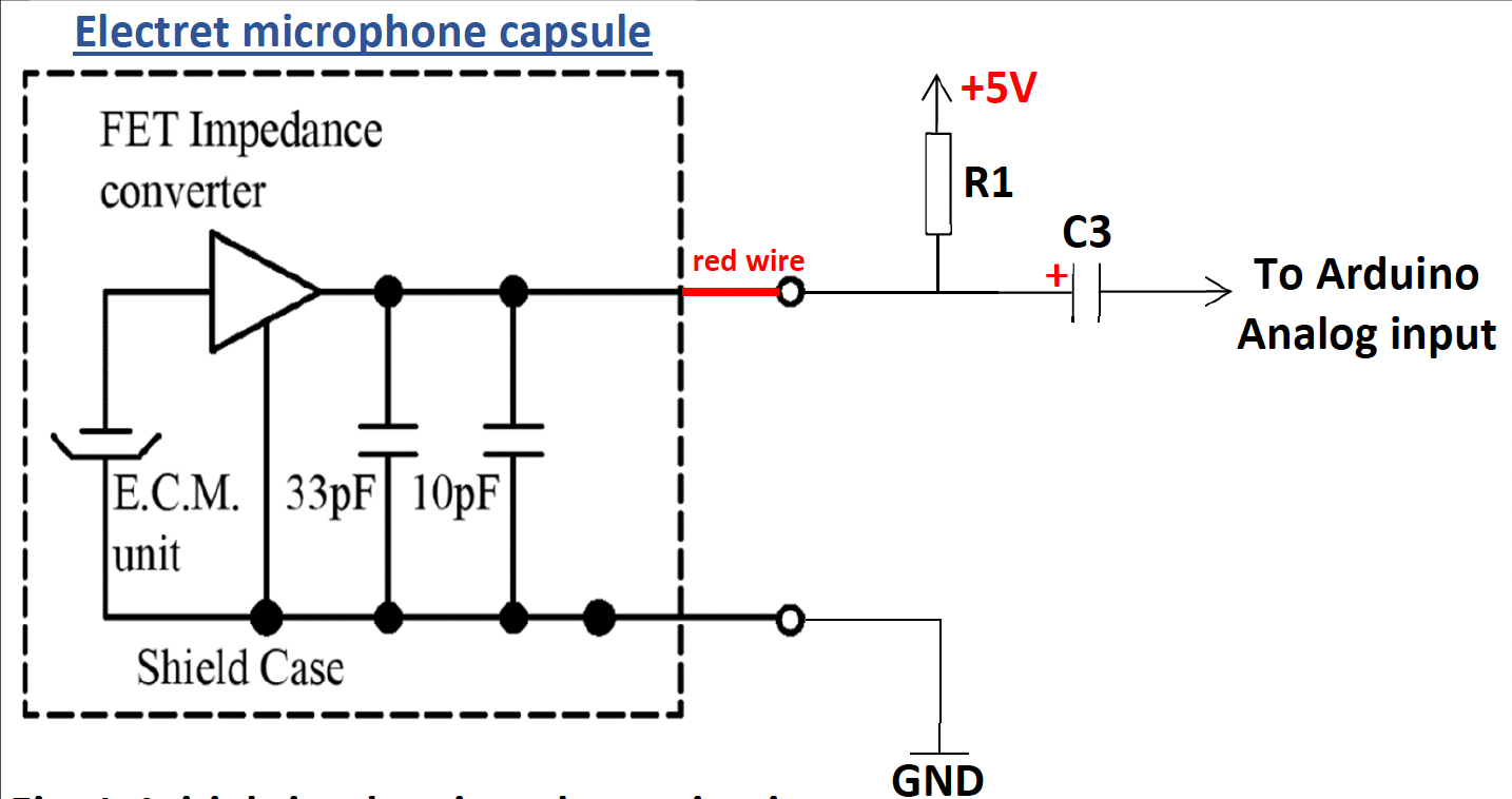
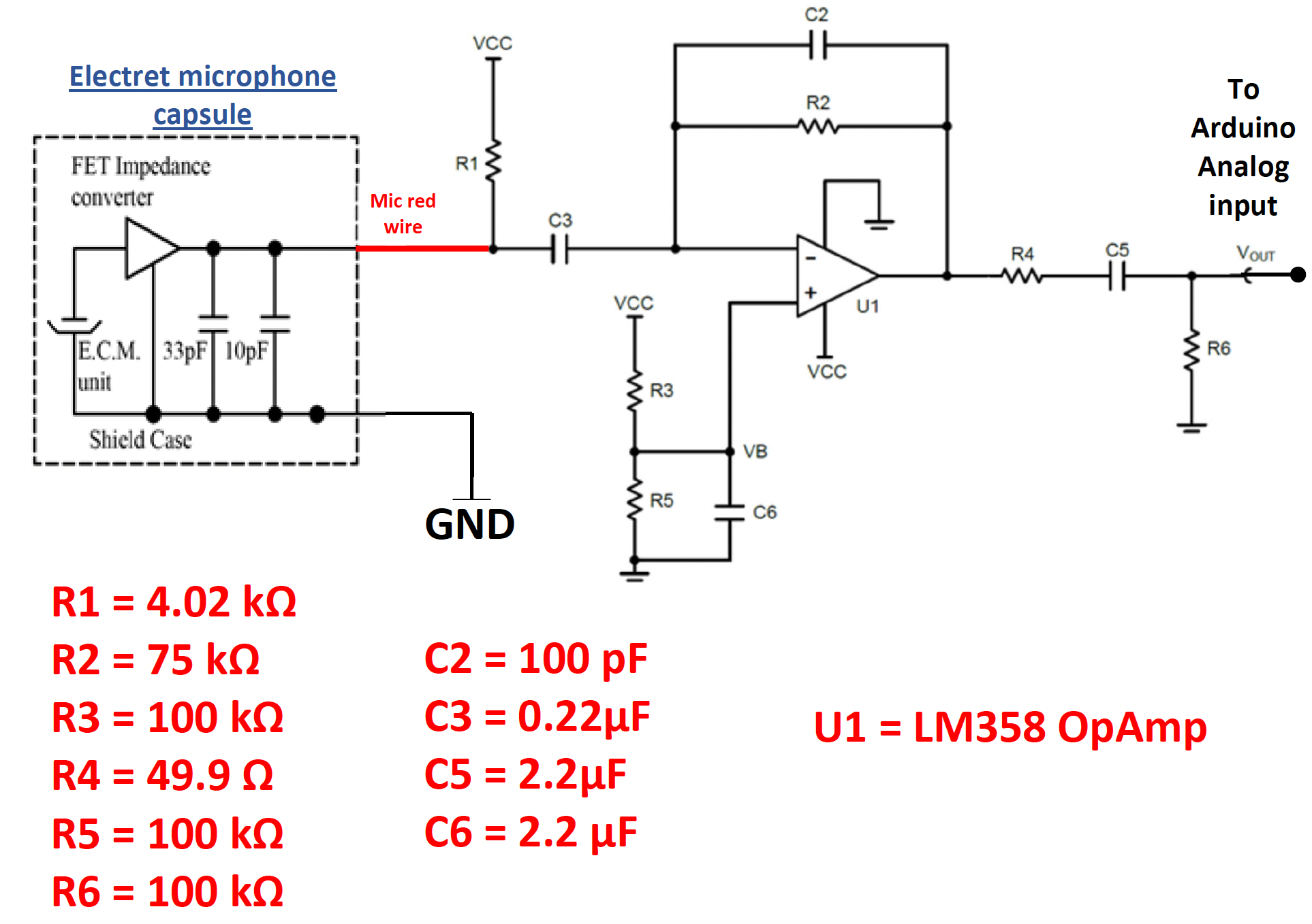
We then built a basic microphone circuit that could collect sound that was eventually processed by the Arduino Nano on the robot by soldering a piece of jumper wire at the end of each lead of the microphone and assembling a circuit on the main breadboard using a Resistor of 4.02k Ohms and a Capacitor of 0.22 microFarads as outlined on the circuit diagram below.
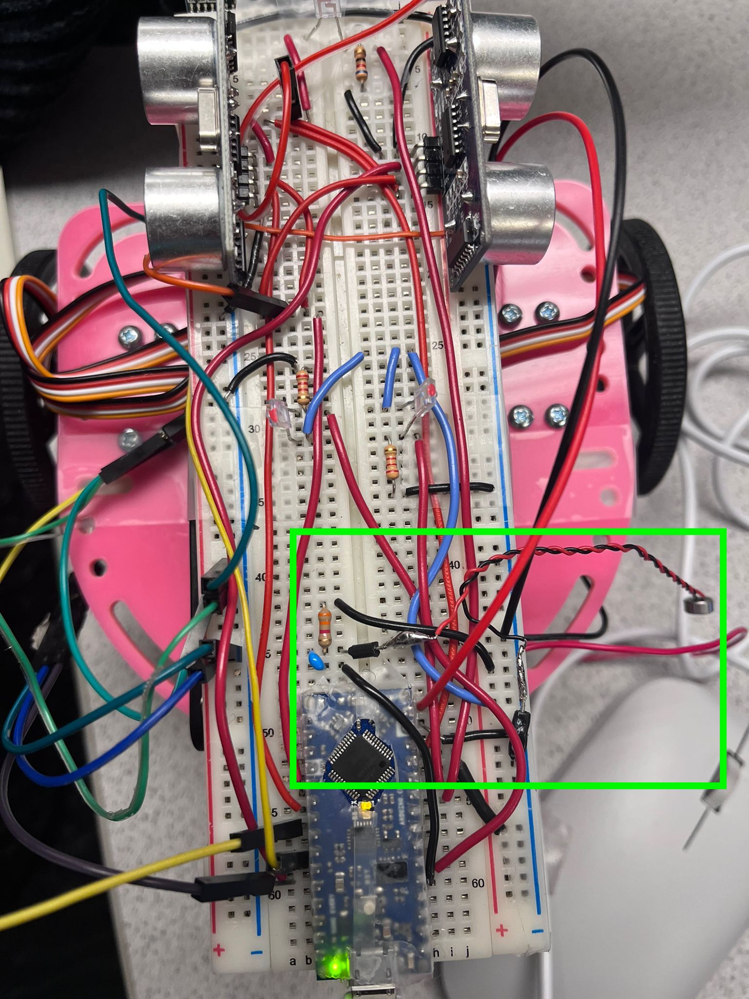
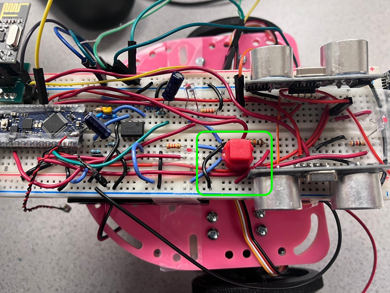
Below shows the microphone circuit (highlighted by the colored box) without Amplification as connected on the main breadboard:
After building the microphone circuit, we coded the Nano to collect sound played by a MATLAB file from the microphone circuit, which were read by the Arduino Analog-To-Digital converter (ADC) and sent to MATLAB for analysis via the USB cable with the command read.
MATLAB graph spectrum from Fourier analysis from the non-amplified circuit:
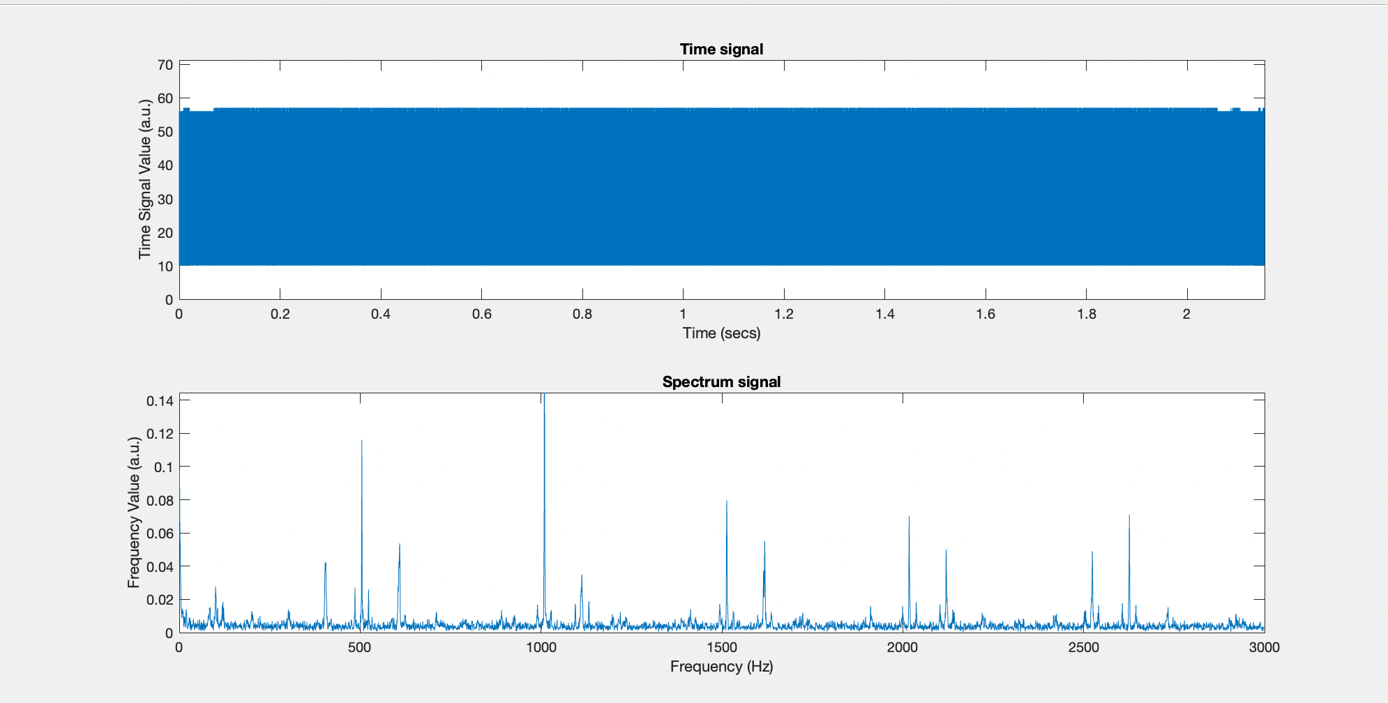
Since the spectrum’s value at the frequency of 500Hz is relatively weak, the sound picked up by the microphone needs to be amplified. Therefore, we constructed an amplified microphone circuit in place of the basic non-amplified microphone circuit on the main breadboard as outlined on the circuit diagram below.
Below shows the amplified microphone circuit (highlighted by the colored box) as connected on the main breadboard:
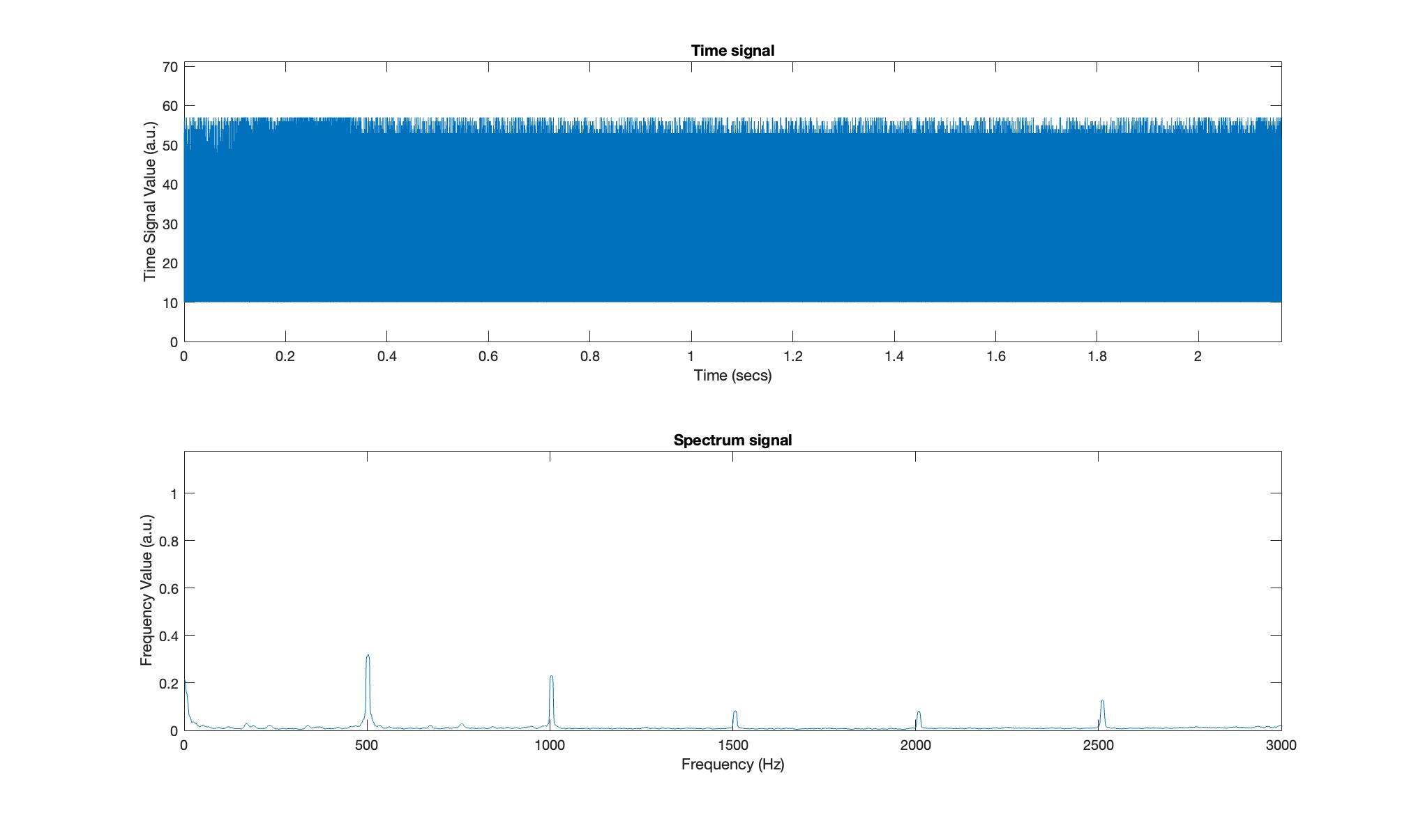
We also used MATLAB to analyze the sound collected by the Nano for the amplified microphone circuit and below is a graph showing the spectrum of the Fourier analysis as output by MATLAB:
Since the Fourier Analysis would be performed on the Arduino Nano rather than the MATLAB, we coded the Nano to perform the analysis and tested the code by visulaizing the output spectrum through playing a sound only MATLAB file.
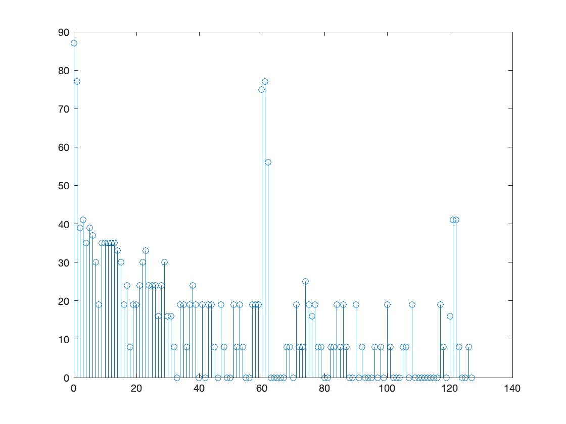
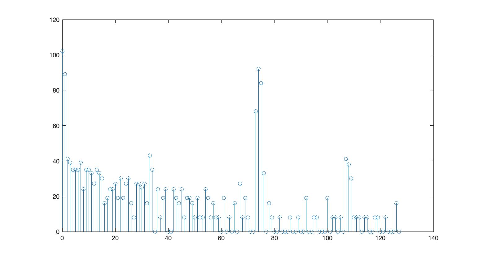
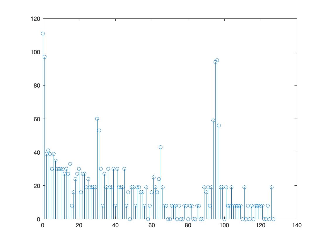
Graphs below x-> bin number & y-> Amplitude(a.u.)
Spectrum obtained with Nano for a sound frequency of 500Hz
Spectrum obtained with Nano for a sound frequency of 700Hz
Spectrum obtained with Nano for a sound frequency of 900Hz
After the analysis, we installed an overrride button that could be used to signify the robot to start navigating when the trigger frequency is played as highlighted by the box in the image below.
