Intelligent-Physical-Systems
Project maintained by jim59 Hosted on GitHub Pages — Theme by mattgraham
Lab 4
For this lab we worked on adding a number of functionalities to the robot:
- RF communication between the robot and the base station that contains a 7-segment display and an RF antennae that receives a sigal from the robot and displays a frequency value
- re-coded blocking statements by changing the program to not run on delay() statements
- finalized the onboard FFT (Fast Fourier Transform) and installed an override start button
- implemented a navigation algorithm that the robot would use to navigate the maze
- implemented PID control to help the robot to adjust its motion and prevent obstacles with walls of navigation
- ensure that a treasure’s measured frequency will be displayed on the base station
- ensure that the ultrasonic sensors, phototransistors and microphone circuits operate and provide necessary inputs to the robot
Accomplishment: Since this was our final lab we were able to test out the robot’s navigation on the maze.
- Using the amplifier microphone the robot was able to detect a 440Hz sound to start navigating (the override button installed was a backup in case the robot would not move when the frequency is played)
- We were to establish an RF communication between BotMobile and the base station were treasure freqeuncies would be displayed
- We callibrated a PID (Proportional Derivative Integral) control for BotMobile to correct its motion during navigation
- Navigation was the hardest part of the whole implementation that we did not get working quite as well. However, we were able to use DFS (Depth-First Search) algorithm for the robot to navigate throught the maze
Phase I
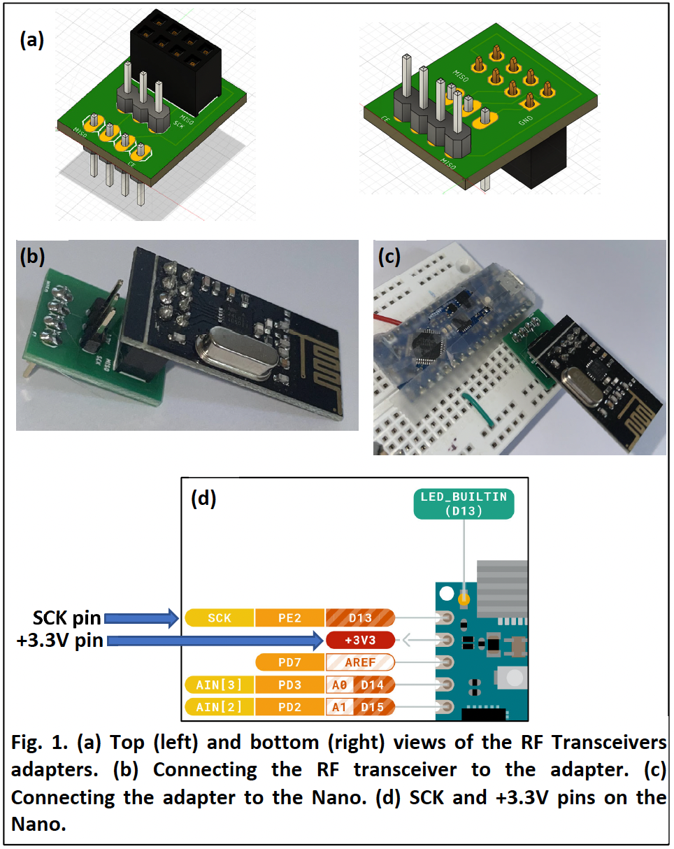
For the first phase of this lab, we connected the RF Transceivers to the main breadboard on BotMobile and the basestation. The RF Transcievers were connected to the breadboards using an adapter as shown on the image below.
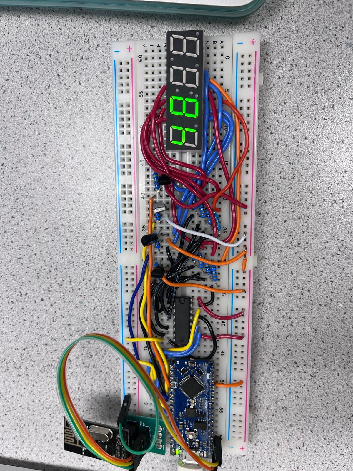
- An image of the Base station:
After connecting the RF Transceivers, we tested them on the Arduino IDE using the RF24 library to check if the communication between the main breadboard and the basestation works.
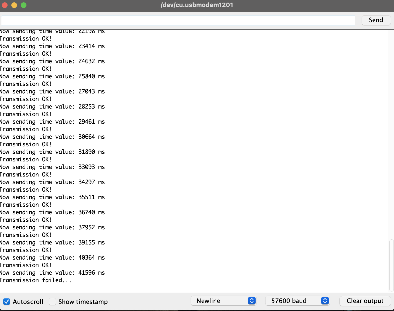
- We test the transmission by sending wirelessly the value of millis() every 2 seconds and use the Serial Monitor to view whether the Transmission was successful or not.
- We also experimented on the signal strenght by changing the distance between the robot and the base station to see when data is not received.
- The image below shows the Serial Monitor output as the RF Transceiver on the main robot sends the signal to the Basestation
Next, we changed the blocking statements in our Arduino code by subtituting the use of the delay() function to use conditional statements and variables using timing functions, such as millis() or micros().
After connecting the RF Transceivers and Non-Blocking Code, we worked on the FFT & Override button that when implemented enabled BotMobile to remain motionless unless triggered by a 440Hz (detected by the microphone) that signals the robot to start navigating. In case BotMobile does not start to move by the end of the melody, we use the override button to signify the robot to start navigating.
Phase II
Pid Control & Frequency Measurement
Before implementing the navigation part of the project, we first worked on the PID Control so as to tune the robot to correct its motion and avoid obstacles while moving. The other reason is because it is easier to determine the changes caused by different PID constants, which would be hard to debug when PID control is tested with a complex navigation algorithm.
- The PID control uses feedback from the left, right, and front Ultrasonic sensors to adjust the speed of servo motors to regulate its position on the naviagtion path, an adjustment that enables autonomous navigation.
After tuning the PID control, we worked on the Frequency Measurement & Display that enable the robot to lookout for two treasures on the maze that emit specific freqeuncies & have their LEDs as height approximately equal to the phototranistors on the main breadboard. The measured value of the frequency of a given treasure must be sent wirelessly to the Basestation so that the latter can be display the frequency as soon as possible from when the robot finds the treasure.
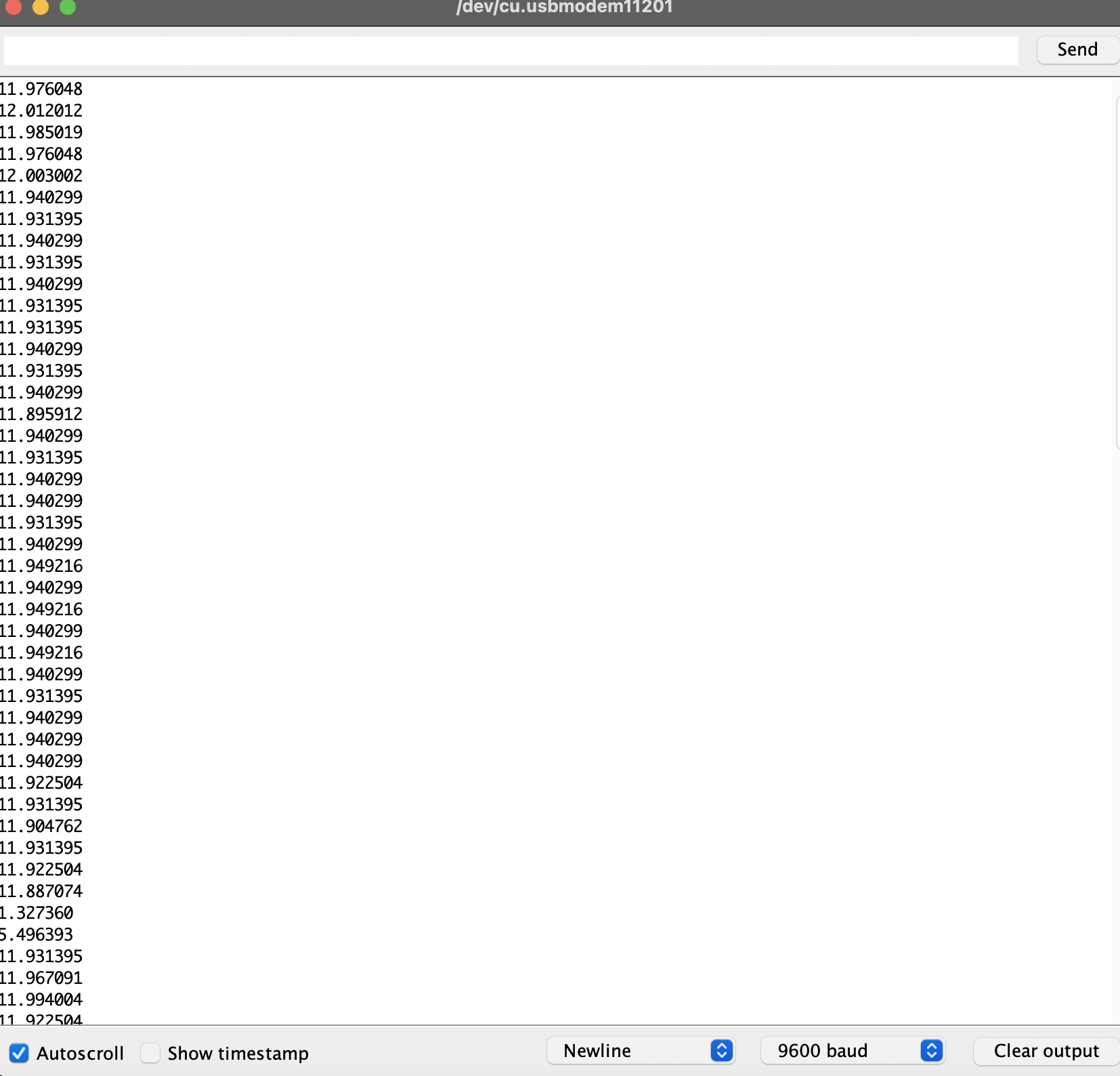
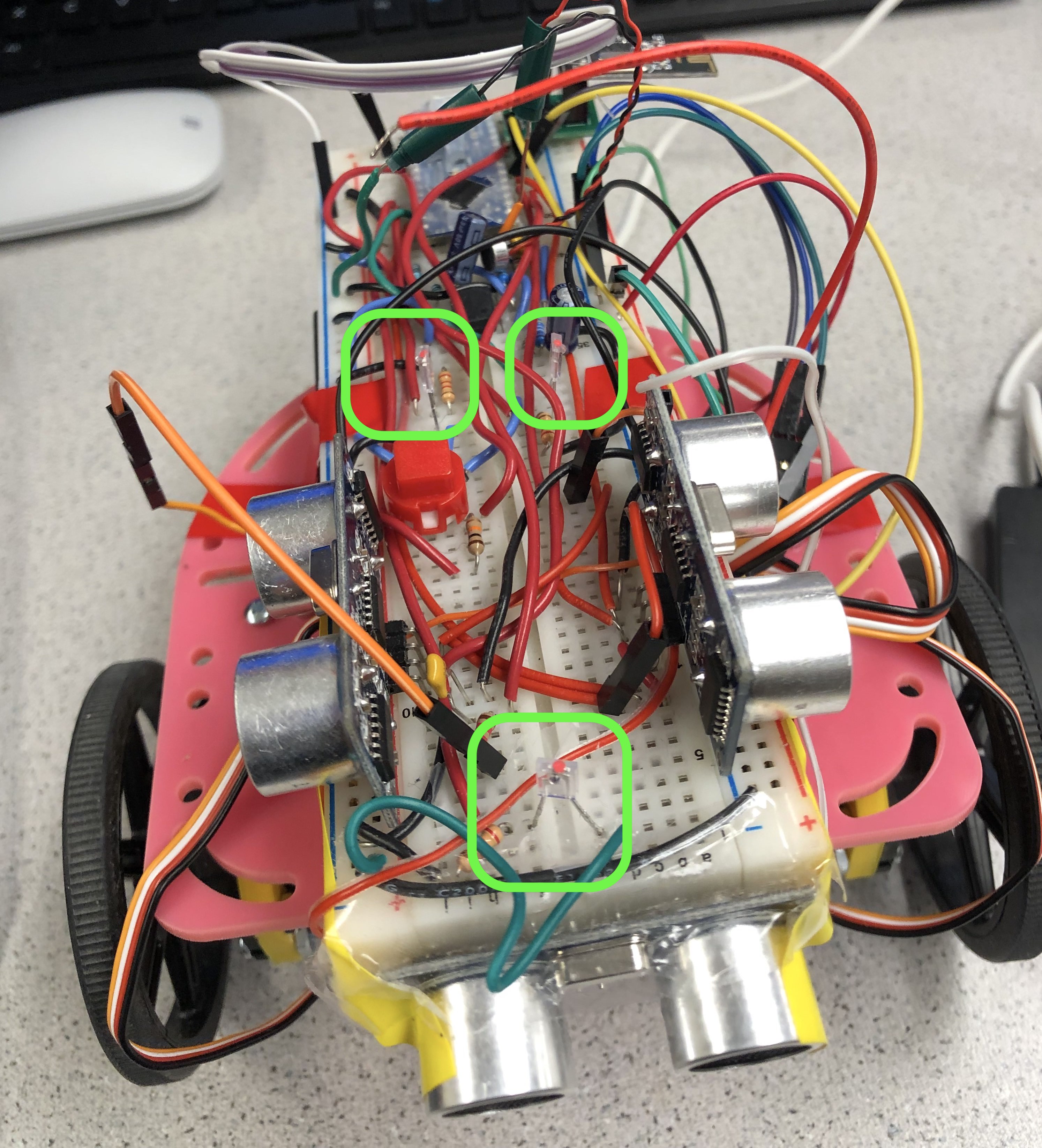
This frequency detection of the treasures was made possible by three phototransistors (left, right, & front) that we tested out for frequency detection by using a signal generator and displaying the results on the Serial Monitor.
- This image shows the left, right and front phototransistors on the main breadboard on BotMobile, highlighted by the colored shapes
Phase III
For the last phase of this lab & the final phase of the project, we worked on Navigation, which proved to be the most challenging part of the whole process.
We implemented the Navigation using the DFS algorithm for the robot to navigate “intelligently”. The main function of the robot is to navigate the maze, detect the frequencies of two treasures, display the frequencies on the base station, and stop naviagting immediately after the second treasure is found.
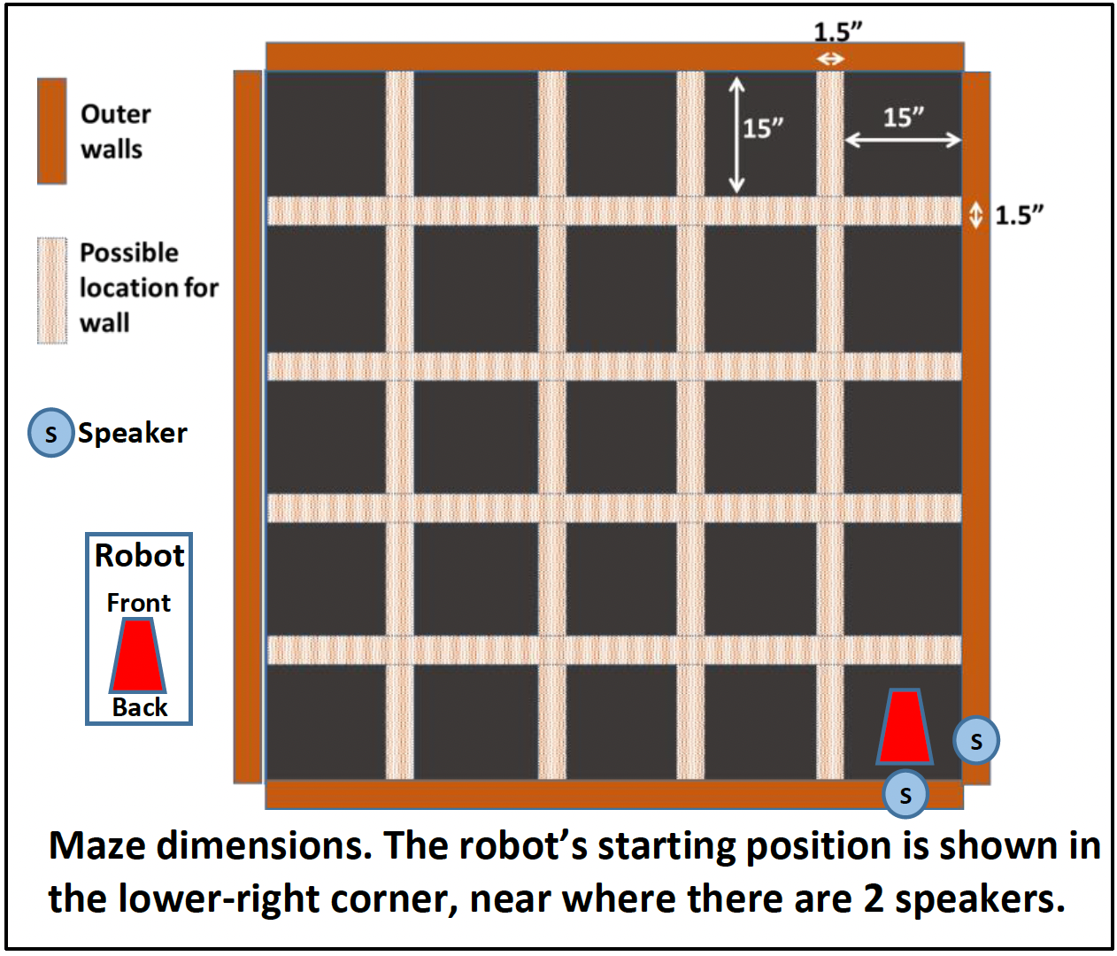
- The image below shows a simple blueprint of the maze with speakers that play a sound and signal the robot to move when a 440Hz frequency is heard.
I would like to conclude this report by quoting Murphy’s First Law: “Anything that can go wrong will go wrong” and such was the case for the Navigation phase of this project. Although we spent hours debugging and were able to get the DFS algorithm and robot motion to partially work, we could not get the robot to fully navigate and as an engineer I know nothing can get worse from here, just better.
So below is a short video of the recorded attempt: Thanks.
(Much better attempts were made but this is was one of the recorded few just to give you an idea of the navigation portion)