Objectives
- Effectively transfer data between the robot and computer
- Implement a functional PID
- Complete Task A: Don't Hit the Wall
Prelab
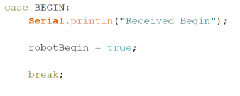
Before the lab, I needed to prepare the robot's BLE (Bluetooth Low Energy) to begin by a command sent from the computer, and when the robot finishes its task, transfer the time, TOF readings, and motor input values to the computer to be analyzed. Beginning on a command was straight forward. I simply added an additional command type, that when called on the computer would set a global variable to true, so that the robot would begin its task. Below is my code that implemented this fucntionality.

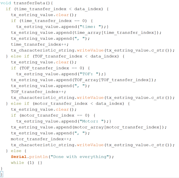
Next, I coded how to send data to the computer. While preforming the task, the values for the time, TOF readings, and motor inputs would be added to their respective arrays. After the robot completed the task, the robot would then transfer the data in the arrays. I implemented the code in a way so that it would be easy to copy and paste into the graphing functions of the Jupyter Lab. I transfered the data in strings so that more information could be sent. I also had to code a string handler function on the Jupyter Lab side so that it would receive the data automatically. Below is my code.

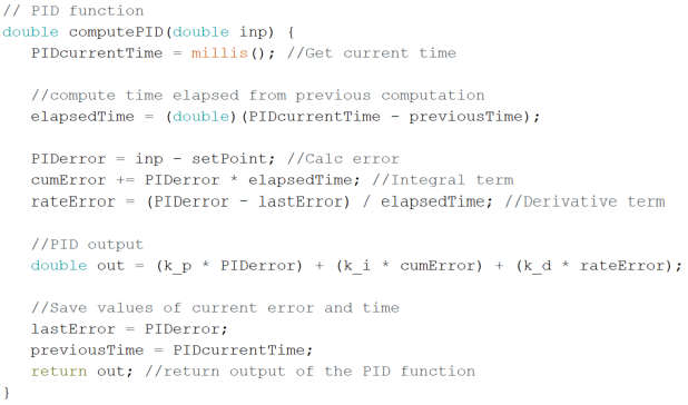
Finally, as the last part of the Prelab, I implemented my PID code, which is shown below.
Task A: Don’t Hit the Wall
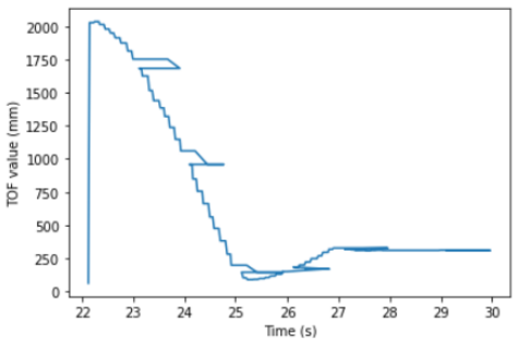
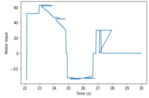
The task I chose to do is Don't Hit the Wall. The goal is to start the robot from far away, then drive up to the wall and stop around 300mm before the wall. The only sensor that is required to use for this task is the front facing TOF sensor. Since the goal is to drive to a specific close distance to the wall, I used the short distance mode to get more accurate readings near the stop point. I set my set point for the PID to be 300mm, and I coded a function to convert the PID values to respective motor values. My function changes depending on what the max speed you want; I went with a max motor input of 65, so my function came out to .002333 * |PIDoutput| + 30, where 30 is the deadband value. This function also included a situation where if the PID output is near zero, it would active break. Using the most basic PID (proportional = 1, integral = 0, derivative = 0), my approach proved successful. Below is the video shwoing such and respective graphs.
Tuning the PID
To start tuning my PID, I set my proportional constant to .75, .5, and .4. After a few run throughs using these values, I found .5 gave me the best results, in terms of overshoot and oscillation, and was the most reliable. Below is a video of my proportional constant set to .5 run followed by the graphs of the data.
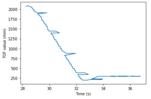
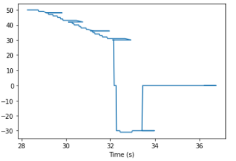
As you can see, the overshoot is minimized without sacrificing too much speed, as compared to the 1 proportional constant.
Based on prior experience with working with a PID controller, I had more success with the derivative term than with the integral term, so I decided to implement the
derivative term next. To start off, I set my derivative constant to .1, .2, and .3. Once again, after a lot of testing, I decided that setting the derivative constant
to .2 gave me the best results. Below are some videoes of my test runs run followed by the graphs of the data.
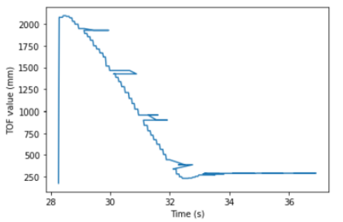
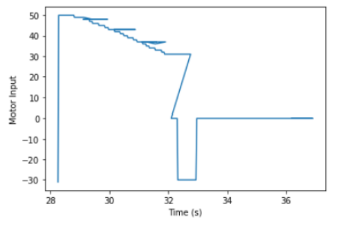
Above is the .3 test run
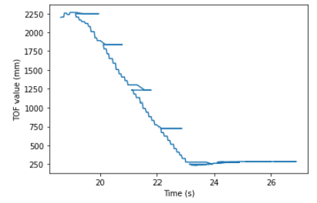
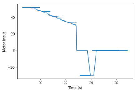
Above is the .2 test run. There is barely any overshoot, and the robot smoothly drives to the desired distance from the wall. Also, I implented my PID in such a way so that there would be no derivative kick, and I did not see a benefit in implementing a derivative low pass filter.
Finally, I moved onto the intrgal part of the PID controller. After a lot of experimenting with values, I noticed that the integral constant either had little to no effect, or made the robot go totally out of control, even after avoiding wind up. I decided it would be best to just leave the PID controller as simple as possible, so I just went with PD controller with values of .5 and .2 respectively. Below is another video of my robot running as expected, so to prove that the contoller and values I chose are reliable.
Preformance
The preformance of the robot is determined by the ToF sampling rate, and control loop processing rate. The ToF sensor takes some time to record a distance, so one tradeoff I had to consider was reducing accuracy in order for a faster sensor sampling rate. After experiementing, I decided to keep the sampling rate default because my robot was not traveling at speeds where there were major errors in the ToF data. I alsp made sure to get rid of any waiting functionality tied to the ToF sensors. Additionally, I kept my loop as simple as possible to make sure my control loop sampling rate was optimal. This means I did not use any BLE functionality while the robot was moving, or any other unneccessary lines of code like print statements.
Important Note
I have no idea why the graphs have those weird horizontal spikes. I checked my arrays to make sure no values were switched in any places, but I could not find any issues.