Objectives
- Implement a controller so that the robot turns consistantly
- Gather data in a rotation and use Bluetooth to transmit it to your computer
- Process and analyze the data
Control
The goal of this lab is turn 360 degrees and gather ToF data at approximately every 20 degrees. In order to recognize when the robot had turned 20 degrees, I used the gyroscope data and integrated it. One issue I had when making sure the calculated degrees was accurate, was that there was significant drift. To mitigate this, I implememted a low pass filter that would zero gyroscopic values that had a magintude of less than 2 degrees per second. Additionally, after the robot turned 20 degrees, I would zero all my calculations to essentially reduce any build up of error. To control my turns, I simply turned the robot at a medium speed until it reached 20 degrees, then stopped for half a second to gather data. I opted to not use PID control becuase the turning functionality on the car was very inconsistent, and implemneting it would complicated turning even more. However, even after implemnting the low pass filter and other methods to increase the accuracy of the gyroscope, my robot did not turn 360 degrees in 18 turns. Instead, my robot turned consistently 14 times at 25 degrees each and completed a full 360. After a lot of adjusting, I could not get the robot to accurately turn 360 degrees with more stops inbetween, so I just decided to proeceed with my 14 points in one turn. Below is a video showing my robot's ability turn accurately.
Data Collection
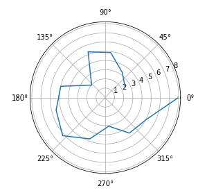
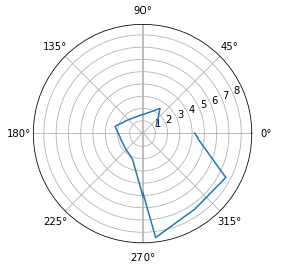
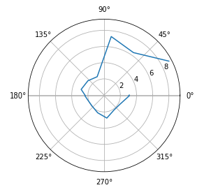
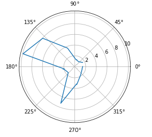
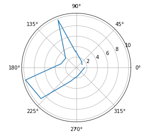
Just like in previous labs, I used Bluetooth to control the robot wirelessly, like to tell the robot to start and to receive data. In my motion loop, I only saved data to arrays, and transmitted the data after the movement was completed to reduce the loop time and improve accuracy of the gyroscope. I placed my robot on the five spots in the room, and collected data in each spot serveral times to get precise scans. Below shows my polar coordinate plots for each of the five spots.
Transforming Data and Plotting
Since the data received is in polar coordinates and millimeters, I used trigonometry to convert them into rectangular coordinates, and a conversion factor 1/305 to convert millimeters to feet. Additionally, I had to translate each coordinate with respect to the origin of the room because data was recorded at different points. I then plotted all my rectangular points onto a singular graph which is shown below. The blue lines is the coordinates of the actual walls, and the red is my predicted walls.
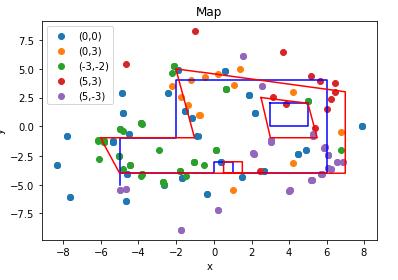
As you can see, my robot's ToF readings were not very accurate. There are a lot of stray data points outside of the clumped areas. To increase my accuracy, my robot
could have taken more measurements in a turn, or maybe even completed multiple rotations and averaged out the readings.