Fig. 1. GUI of the Arduino IDE.
Lab 1 is the first part of building a light-following robot, and the following will take place in lab 2. The light-following robot should do the following:
In this lab, we successfully accomplished:
blink_LED.ino)At this point, the robot has the inputs needed to know where the light source is coming from, and the remaining (including control of the motors, etc.) will go into lab 2.
This lab 1 report will therefore be organized into four main sections, each discussing one of the tasks above. The Discussion section at the end recaps the goals of this lab and discuss future directions.
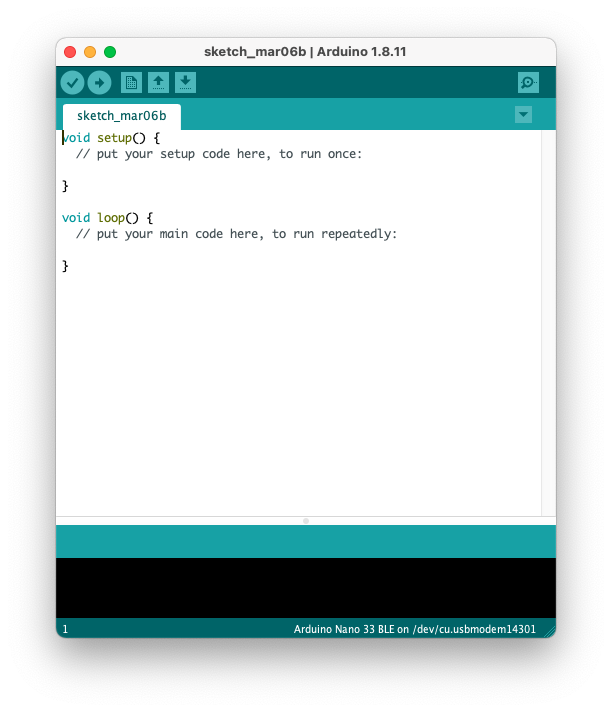
It is undoubtedly important to set up the development environment before we can do anything. The lab handout documents the use of the Arduino IDE (See Fig. 1) for coding, compilation, and deployment. However, I found the Arduino IDE having the following caveats:
Fig. 1. GUI of the Arduino IDE.
To address these problems, I embraced PlatformIO (See Fig. 2) in Visual Studio Code as my development environment. PlatformIO retains the ease of library management and one-click build-deploy process just like that in the Arduino IDE while perserving a full C++ experience with a lot of customizability (and support for on-board debugging, unit-testing, and VS Code extensions). Therefore, I determine that it is a better workflow for me who already has some experience working with C++ and Arduino boards.
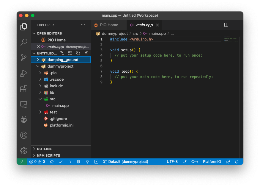
Fig. 2. GUI of the PlatformIO extension in VS Code. Note that files have .cpp suffix, and the project directory is organized in a more sophisticated manner.
In all other parts of this lab, I am able to finish all the activities with PlatformIO, and I expect the rest of the labs will be accomplished with PlatformIO.
In this section, an example program, blink_LED.ino, is uploaded to the board to blink the on-board LED. The example file is in the .ino format, so I had to adapt the example file for a C++ implementation. This is easy, – simply copy-paste all the contents in setup() and loop() of blink_LED.ino to main.cpp and click the “check” and “arrow” buttons in the lower left corder of Fig. 2. These two buttons do the exact same function as that in the Arduino IDE: compile and upload to the board. With PlatformIO, it automatically selects the USB port, and will prompt to manual selection if there are two identical boards connected to the same host computer. After verifying by seeing the LEDs blinking on the board, I am convinced that PlatformIO can serve as an alternative workflow of that described in the lab handout.
For the robot to move towards the light that is brighter, there must exist an “information channel” between the robot and the environment around it. At a high level, we know that light sources are analog input (unless we are doing single photon detection, whose nature is still analog considering the state of the photon), therefore, no matter what kind of sensor we use to sense the environment, we need analog-to-digital converters (ADCs) in the light-following robot. Because this is an ECE course (and some other reasons), the ADCs discussed within the scope of this wiki are voltage ADCs. Luckily, the ATMega4809 microcontroller in our Arduino nano every development board has integrated ADC (see ATMega4809 datasheet for more details). In the Arduino development environment, pins wired to the ADCs are called “Analog” pins. The Arduino compiler also has functions like analogRead(pinNum) to make interactions with the ADC easier (avoid dealing with config registers).
Reading values from the ADC is fairly easy. A pin value and an analog value variable are first decalred, both as int type. Then the function analogRead() is called, which takes the pin value as input and stores the analog value of the pin into the analog value variable. The code snippet below does exactly that.
int pinValue = A0;
int A0Value;
A0Value = analogRead(pinValue);
This code snippet reads the value of pin A0 and stores into the variable A0Value. It is worth noting that unlike a DMM, the ADC is not capable of reading the absolute voltage! For the ADC that comes with ATMega4809, the digital output from reading an analog input is indeed
Result = 1023 x Vin / Vref,
where Vin is the input voltage, and Vref is the reference voltage. The default selection of Vref (as verified in the lab activity) is Vdd, which is the USB input voltage when the Arduino board is powered by USB. In the lab activity, we also verified the voltage of Vdd by measuring the 3.3 V output on the board and print results from the UART monitor on the computer. With 3.3 V being Vin, the result is ~670, translating to Vref = 1023 x 3.3 V / 670 = 5.03 V. We determine that this voltage is within a safe range, and we proceed without taking any adjustments.
Now we know how to measure voltage with the Arduino board, we need to incorporate light sensors into our design so that the robot can sense the presence of light (wow exciting!). The light sensors we have in hands are CdS photoresistors. The resistance of these resistors changes with changing lighting conditions. In dark environments, the resistance is ~1MOhms, while the resistance can drop to several thousand Ohms when a flashlight is directed toward the sensors.
Because the ADCs cannot directly measure the resistance, we use a voltage divider circuit (see Fig. 3) to detect the variation in photoresistance. With the circuit in Fig. 3, change of photoresistance changes the voltage at Vout, which is detected by the ADC. The robot is then able to sense light!
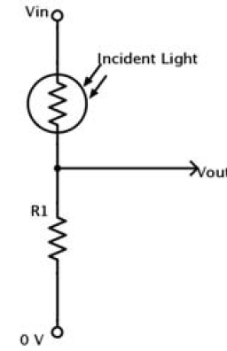
Fig. 3. Voltage divider circuit. Vout goes into the ADC pin on the Arduino board. The change of photoresistance changes the voltage at Vout, and therefore the ADC result changes as the photoresistance varies. The robot is then able to detect light!
Because the robot needs to turn with respect to the direction of light, it needs two of these sensing circuits. Fig. 4 shows the assembled circuit on a breadboard. The positive power rails are connected to Vdd, and the negative power rails are connected to ground. Pin A0 and pin A1 are used as analog inputs connected to the sensing circuits. A higher digital value from the ADC corresponds to brighter light the sensor “sees.”
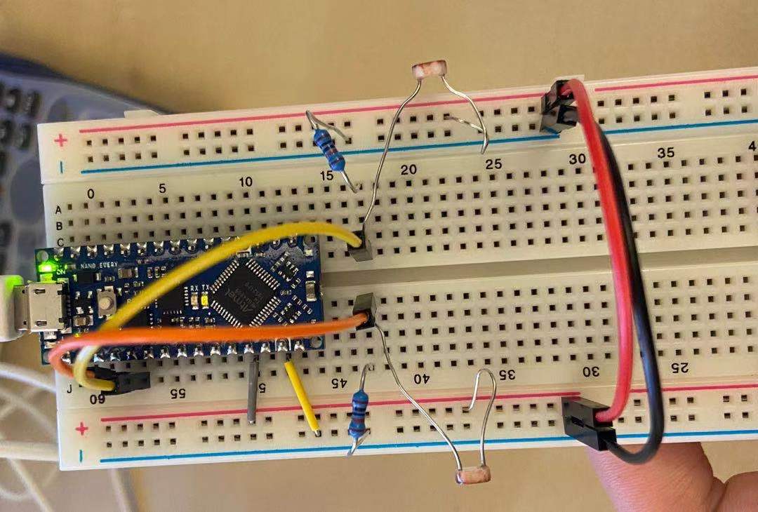
Fig. 4. Two CdS photoresistors connected in sensing circuits. With this setup, the Arduino is able to read the voltage from the voltage divider circuits from pin A0 and A1, and therefore “knows” how much light is present in the surrounding environment.
To avoid recalibrating the sensors when the robot moves between bright/dark ambient lighting conditions, a Normalized Measurement NM is calculated to determine which side of the sensors detect brighter light. The formula is given as
NM_left = SensorReading_left / (SensorReading_left + SensorReading_right)
By comparing NM_left and NM_right, the robot knows which side is brighter (and which way it should turn!). After implementation of the code and the circuit, we tested the functionality by letting the Arduino periodically sending NM values into the UART monitor, and we make the robot either brighter on the left or on the right by positioning our phone flashlight. We also place the robot in dark/bright conditions and observe if the NM values vary by a lot. We saw that the NM values change as expected, and we conclude that our implementation for lab 1 is a success.
In conclusion, we successfully set up the development environment, use on-board ADCs, and use CdS photoresistors to detect light on the robot. We also verify the functionality of the sensor setup. The next step is to control the motors and chain the sensor input and motor response together, finishing the light-following robot!