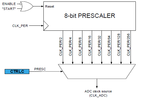
Fig. 1. ADC prescaler. Image taken from the official datasheet of ATMega4809.
Lab 2 is the second part of building a light-following robot. The complete version of the light-following robot should do the following:
In this lab, we successfully accomplished:
This lab 2 report will therefore be organized into four main sections, each discussing one of the tasks above. The Discussion section at the end recaps the goals of this lab.
The ADC (Analog-to-Digital Converter) is a device that converts analog signals to digital signals. Because we live in an analog world and microcontrollers are digital devices, such conversion is necessary for the robot to get any continuous signal from the outside world, for example, the strength of light.
The microcontroller’s operation is centered around clock cycles. However, though the ADC is integrated into the microcontroller’s SoC, and they technically share the same clock, the ADC’s nature determines that it needs to run slower than the microcontroller to sample data in a precise way. Therefore, there is a mux that selects a prescaler, and the main clock frequency is divided by this precaler to yield the ADC clock signal (see Fig. 1).
Fig. 1. ADC prescaler. Image taken from the official datasheet of ATMega4809.
In Figure 2, we can clearly see how the clock frequency can be lowered by a prescaler factor.
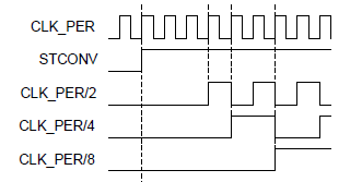
Fig. 2. Lower the CLK_PER (main clock) signal by a prescaler factor.
From a hardware perspective, transistors cannot be switched infinitely fast due to the saturation velocity in silicon and other extrinsic limitations. Therefore, the ADC would lose precision if its clock signal is running too fast. In this part of the lab, we first determine the default prescaler of the on-board ADC. This is done by simply reading the ADC0CTRLC value and referring to the datasheet to see the PRESC bit values. We determine that the default PRESC value is 0b110, which corresponds to 0x6. On the official datasheet of ATMega4809, we found that 0x6 means a division prescaler factor of 128, meaning that if the CPU clock CLK_PER signal has a frequency of 128 MHz (of course it’s impossible for it to go that fast), the ADC clock signal would go as 1 MHz.
We then move on to see how fast we can set the prescaler to be so that the ADC can maintain a 10 bit resolution. In section 29.3.2.2 of the MCU datasheet, there is a message saying that 1.5 MHz is the maximum frequency for which the ADC would be able to maintain a 10-bit resolution. This translates to a minimum prescaler of 16 that can be used.
However, we also tuned the prescaler value to test for the minimum prescaler when the ADC is able to maintain the 10-bit resolution. This is done by connecting the probing pin to the 3.3 V output on the arduino board, and modify the prescaler value.
The ideal ADC readings should be 3.3/5.0 * 1023 = 675. Considering that Vdd is less than 5.0 volt, the actual reading should be higher. We were able to obtain consistent reading of 728 with division prescaler of 8 or higher,while getting reading of 1023 (obviously wrong readings) with lower prescaler values. Therefore, turn out that the Arduino we have obtained is able to keep the 10-bit resolution even with a prescaler of 8, which is better than the stated value in the datasheet.
After doing such experiments with the datasheet, we are more comfortable working with the ADC and it prepares us for future labs where we may need higher sampling rate to boost the performance of the microcontroller.
An H-bridge is a kind of circuit that controls/switches the polarity of the voltage applied. In our case, it helps us controlling the motors because we want the motors to be able to turn in both directions (forward and backwards) so that the robot can perform movements like forwarding, turning, backing up, etc. The specific H-bridge chip that we use is the L293D chip fabricated by Texas instrument. The circuit diagram of the L293D chip is shown in Fig. 3 for reference.
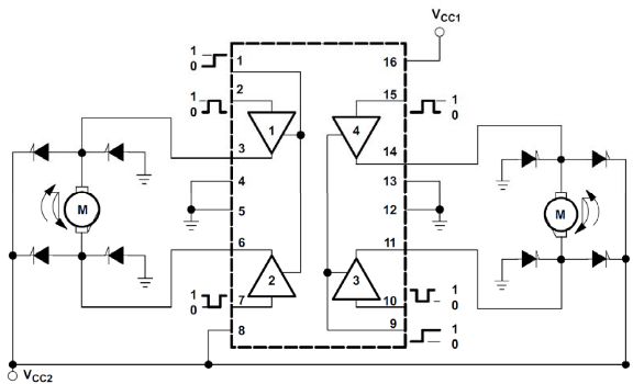
Fig. 3. L293D circuit diagram when controlling motors. Diagram taken from ECE 3400 SP21 slides.
To control the motors, we need to connect the motors and the arduino with the H-bridge IC. Fig. 5 shows an example connection. Pins 1A, 2A are connected to motor A control pins on the arduino, and 4A, 3A are connected to motor B control pins on the arduino. These are digital GPIO pins. Whereas 1Y, 2Y, and 3Y, 4Y pins are connected to the motors. The 1,2EN pin and the 3,4EN pins control the speed of the motor. This is by doing pulse-width-modulation. The higher the duty cycle, the faster the motor turns. These two pins go into the arduino PWM-enabled pins. VCC1 is the power source for internal logic, which is the +5V source from arduino, and the VCC2 pin is the power source used for driving the motor, it is connected to the 4.5V battery array. The other pins go to ground.
To control the direction of the motors, we simply control the lows and highs of the motor direction control pins connected to 1Y, 2Y, 3Y, 4Y on the L293D IC. The specific control for different motor behavior is displayed in Fig. 4. Note that the best way to determine “Right” and “Left” on the diagram is to test out the motor directions, and flip the direction control pins if necessary.
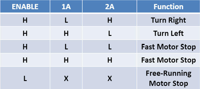
Fig. 4. L293D motor signal control. H denotes high and L denotes low. Diagram taken from ECE 3400 SP21 slides.
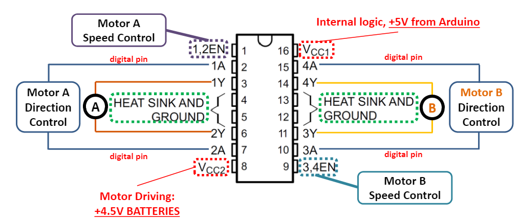
Fig. 5. L293D connection diagram. Diagram taken from ECE 3400 SP21 slides.
After assemble of the robot and writing the corresponding code and helper functions for controlling to robot’s motion, Fig. 6 shows the final connection diagram of the light-following robot with the motors and L293D chip placed on the breadboard and connected to the Arduino development board.
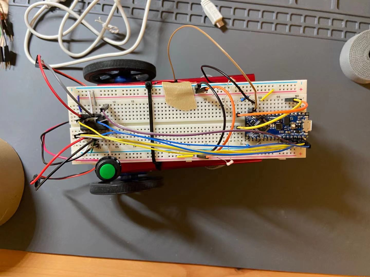
Fig. 6. Light-following robot with L293D IC integrated. A power button is used to turn on-off the power to the motors.
As for the programming part, some helper functions are written to control the robots going different directions. Specifically, we have coded up functions like right_turn(int speed), forward(int speed), back(int speed), to make controlling the robot easier in the future. The speed of the robot is controlled by PWM. There are three preconfigured speed levels, high, low, medium, with each PWM value for different wheels stored in a const array so that the helper control functions can fetch the speed from the const arrays when called instead of manually giving the speed value for both wheels when the function is called.
A demo video is available below showing the wheels turning in both forward, both backward, different directions, and stop. You can play the video on Youtube by clicking the image below.
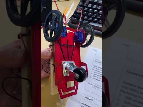
Video. 1. Wheels turning different direcitons showing control of the robot with the H-bridge. Click to play on Youtube.
Because the motors are not exactly the same, there is no guaranteed that the left and right motors will turn in the same speed when given the same voltage. Therefore, calibrations are needed for the three speed levels, low, medium, and high, so that two motors turn the equal amount when given the same speed level.
To do that, we first set the PWM output on the right wheel to be a “standard,” that is by setting low as 70, medium as 150, and high as 255, and try matching the left wheel with the right wheel. This is done by iteratively modifying the code to make the robot go in a straight line when given the same speed level. To speedu up the calibration process, we use a binary search method to locate the best match PWM output of the left wheel. Turns out the left wheel and the right wheel are nearly the same which is off by ±20 for these three speed levels.
Two demonstrations are included in this section: video 2 shows the robot going forward in a straight line in low speed, and video 3 shows the robot going forward in a straight line in medium speed. Note that the video may show the robot advancing in non-constant speeds. This is due to the fact that the floor is not being even.
Video. 2. Robot going slowly forward. Click to play on Youtube.

Video. 3. Robot going forward in medium speed. Click to play on Youtube.
Another thing to note is that the low, medium, and high speed settings for the two wheels are coded into three const int arrays, making future modifications and re-calibration easier as the voltage of the battery drops.
After the motors are calibrated. We were able to finally code up the logic for the light-following robot. We first place the motor controlling functions and the light sensor functions into different files, and have wrapper functions like motor_setup() nad light_senso_setup(). Then in the loop() function, we accomplish three things in each loop: calculating the next state of the robot, toggle the LED on/off logic, and setting the LED state. Each of these three tasks are controlled by their own private timer. For example, the LED on/off logic is toggled every 500 ms, and the next status of the robot is checked every 200 ms. The LED state is set every 10 ms.
In the first task (calculating next state of the robot), the robot would change the motor control pins depending on the lighting condition, and change the LED_enable if needed. Then in the second task, a LED_on flag is flipped because the LED needs to be on/off every 500 ms. Lastly, the third task changes the high/low off the built-in on-board LED depending on the values of LED_enable and LED_on. I have included a pseudocode for how the loop() function is organized.
void loop()
{
  // execute if reaches status change interval
  if (millis() - status_timer >= status_check_interval){
      status_timer = millis();
      // 1. check lighting conditions
      // 2. modify motor control pins
      // 3. modify LED_enable flag if needed
    }
  }

  // toggle LED_on every 500 ms
  if (millis() - LED_timer >= LED_interval){
    LED_timer = millis(); // reset LED timer
    LED_on = !LED_on; // flip LED_on flag
  }

  // set LED state
  if (millis() - LED_response_timer >= LED_response_time){
    LED_response_timer = millis(); // reset LED response timer

    if (!LED_enable){
      // turn off on-board LED
    }
    else{
      if (LED_on){
        // turn on on-board LED
      }
      else{
        // turn off on-board LED
      }
    }
  }
}
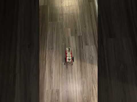
A demo of the light-following robot is shown below. In the video, you can see that the robot is able to do

Video. 4. Light-following robot demo. Click to play on Youtube.
In conclusion, we successfully accomplish all the tasks requred for this lab to build a light-following robot, and we bring our robot to the test ground (my kitchen floor) to try out its functionality. We are impressed by the robust and reliable performance of the robot.
One additional thing to note is that we have also organized our code into librarys for the light sensor and the motor control logics, which we believe will come in handy in future labs!