Tiffany's ECE 3400 webpage
Welcome to my robot-building documentation for Intelligent Physical Systems!
Lab 2: Phototransistors and Display
Summary:
In this lab, we add phototransistors and a base station to our robot. The on-board phototransistors detect infrared(IR) light, which will be useful for our robot to detect the infrared light-emitting ‘treasures’ hidden throughout the maze. The base station contains a digital display which shows the frequency of the IR light detected by each phototransistor.
Task List:
- Build and test IR light detection phototransistor circuit
- Build base station circuit, including 4-digit 7-segment display
Part 1 - Assembling IR-emitting LED circuit
Our first step is to build a circuit that powers an IR LED so that we can use it to check our phototransistor circuit later.
Components of the IR circuit:
- Infrared LED
- 60Ohm Resistor
- Signal Generator
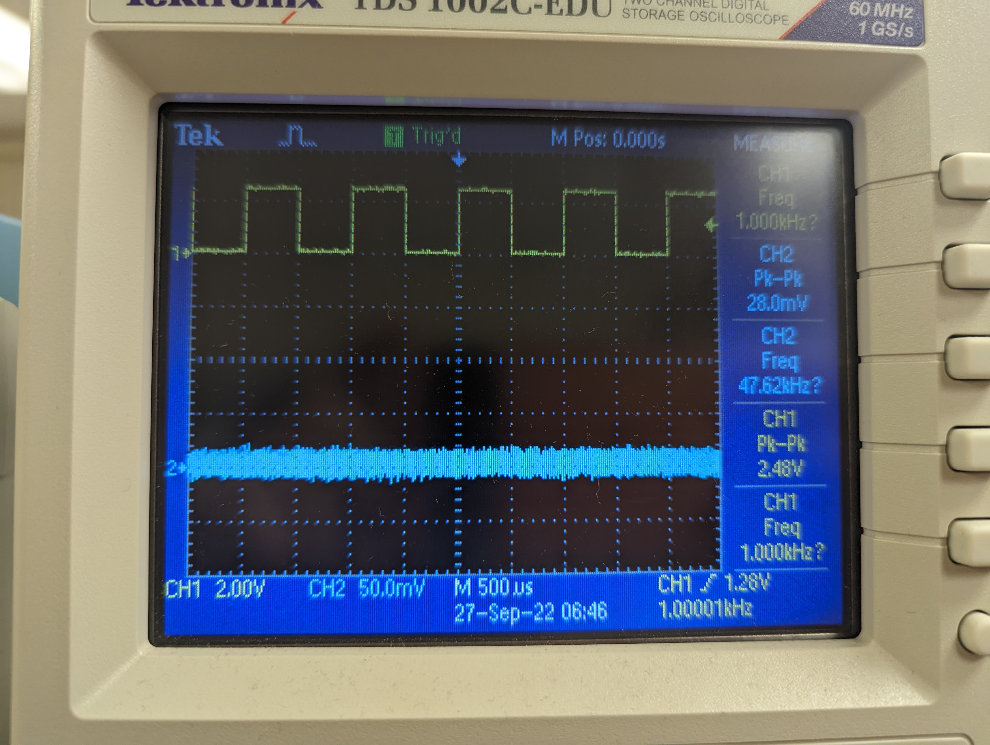
The circuit simply consists of the LED and resistor in series with the signal generator. The signal generator was configured to output a square wave with a peak amplitude of 1.2V, an offset of 600mV, and a frequency of 1kHz.
After assembling the IR circuit, we used an oscilloscope to verify the output waveform that is generated by the signal generator:
Part 2 - Assembling phototransistor circuit
Components of the phototransistor circuit:
- Phototransistor
- 2kOhm Resistor
- 5V power source
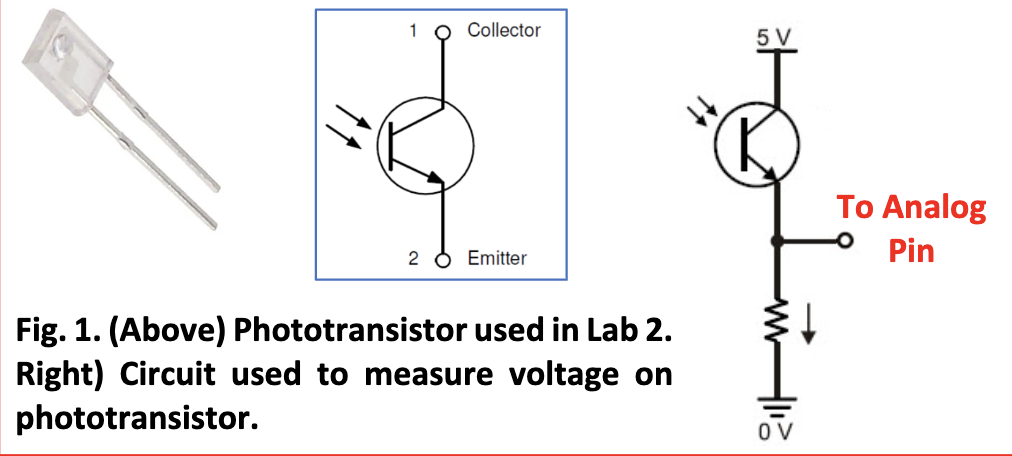
Here is the circuit diagram:
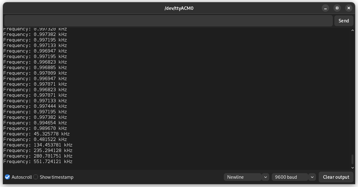
After assembling the phototransistor circuit, we verify its functionality by testing it with the IR LED circuit. Connecting the output voltage of the phototransistor to an analog input of Arduino, we can print the detected frequency values on the serial monitor:
In addition, we also visualized the output of the phototransistor using the oscilloscope. We first output a 1kHz frequency and then a 9kHz frequency from the LED and detect it by placing the phototransistor close to the LED. We used the oscilloscope to display the output voltage waveform:
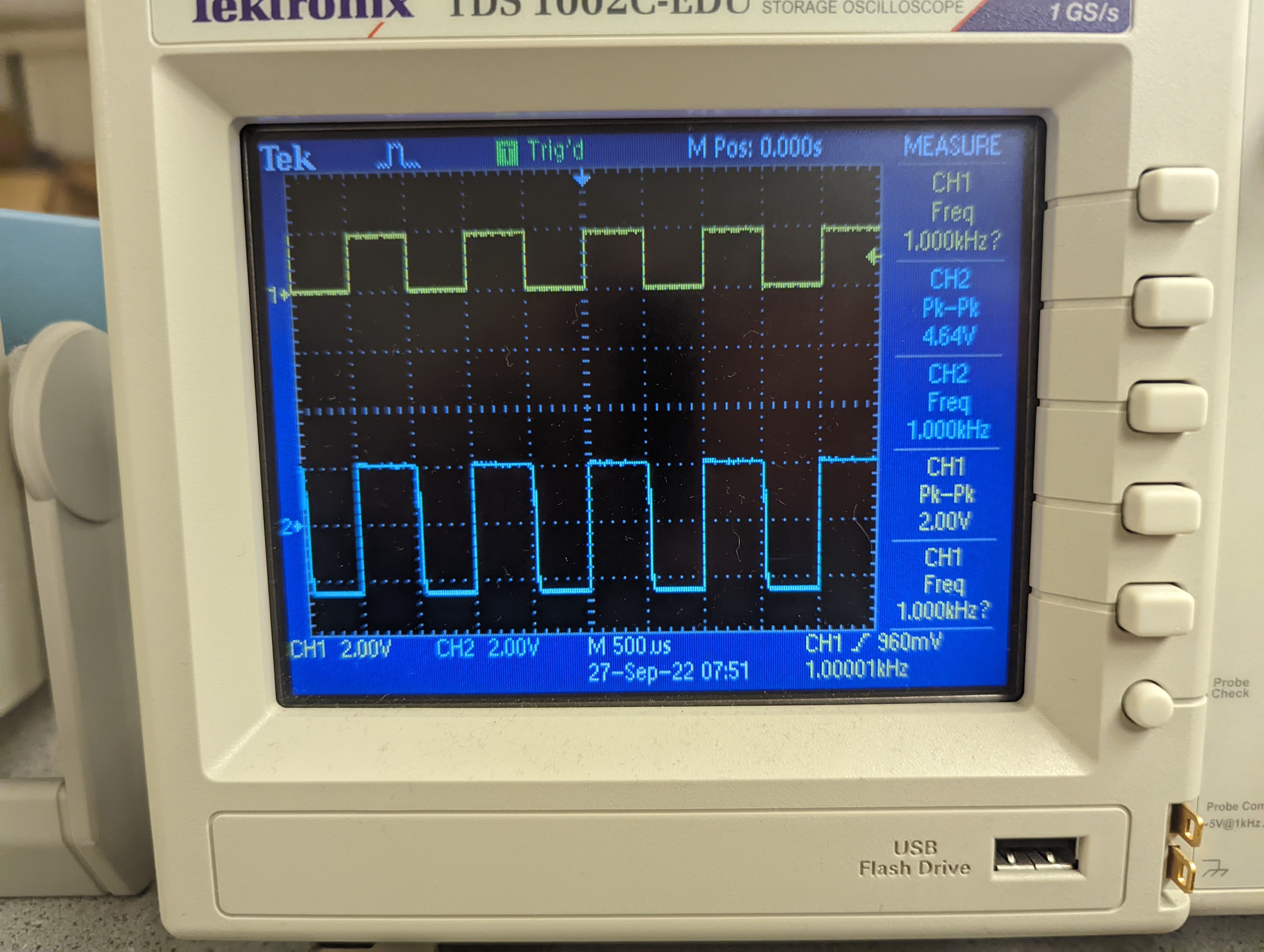
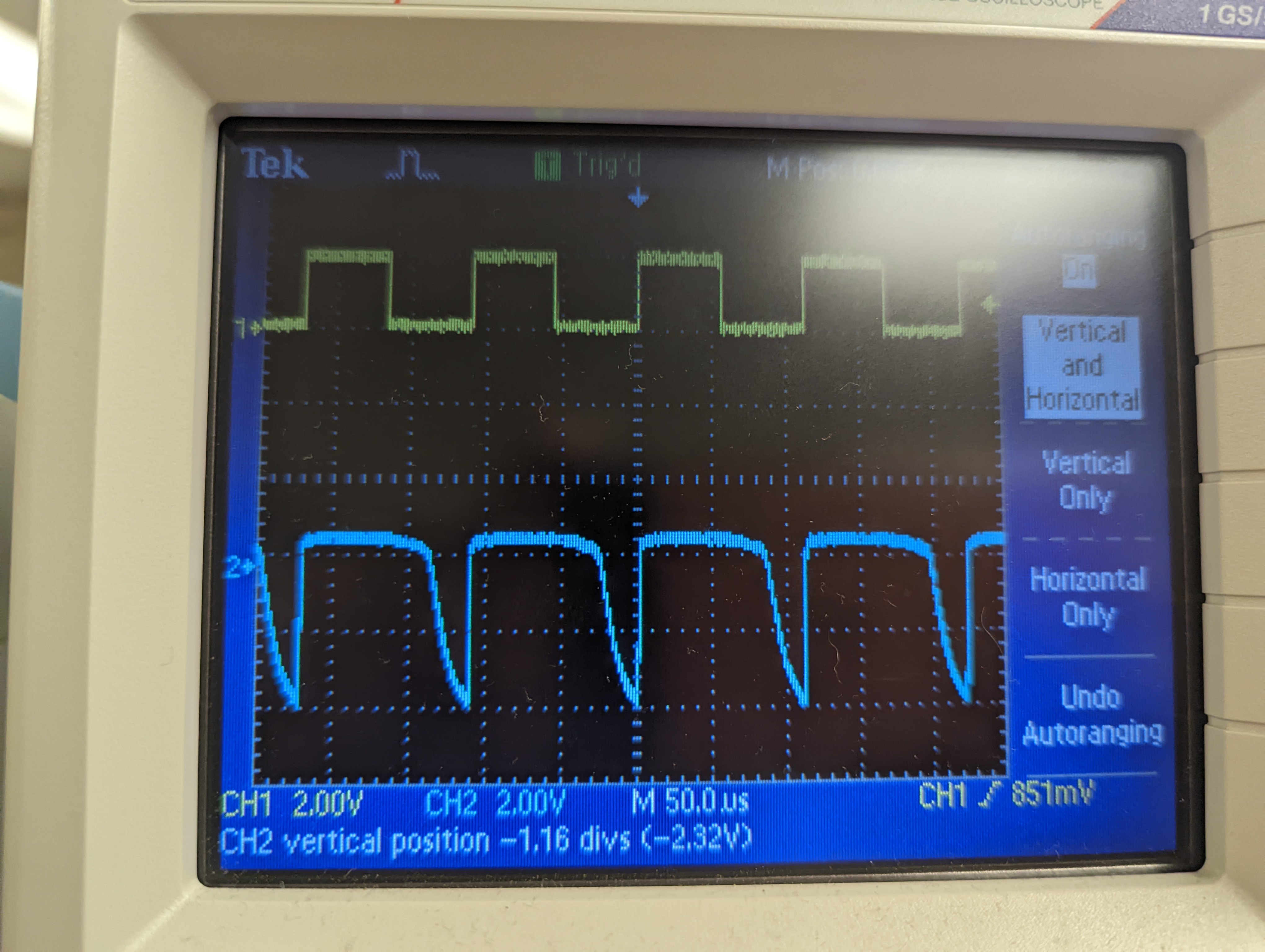
As you can see, some distortion is present in the 9kHz waveform due to the reduced period.
Lastly, we adjusted the DACREF value of the phototransistor voltage reading to account for the effect of ambient light. The phototransistor cannot differentiate the light from the IR LED from ambient light in the room, so we must negate the effect of the ambient light ourselves. Using the phototransistor and the serial monitor, we found the frequency of the ambient light in the room and adjusted the DACREF value in our code so that the output voltage reading only reflects the frequency of the IR LED.
Part 3 - 7-Segment Display
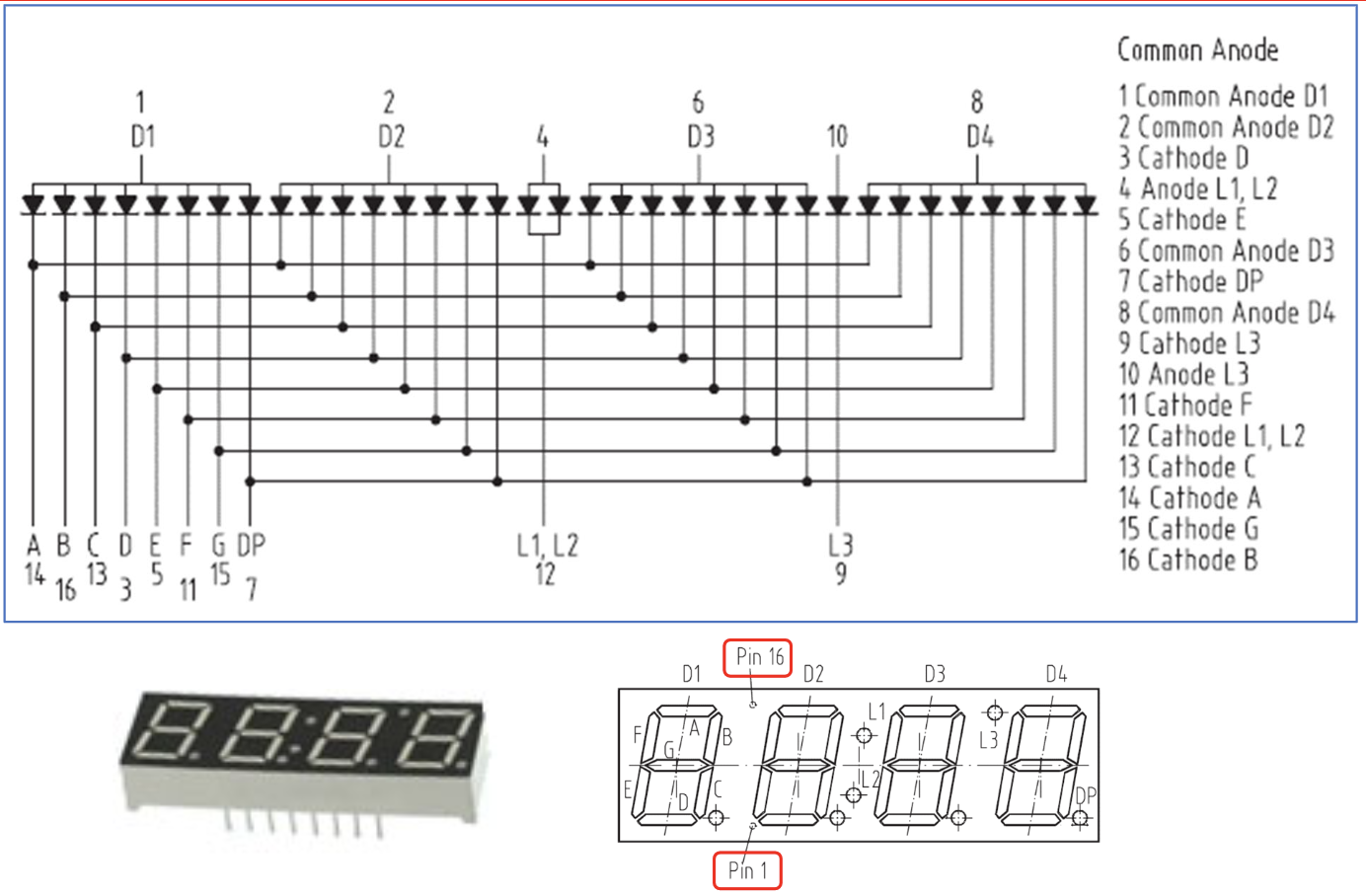
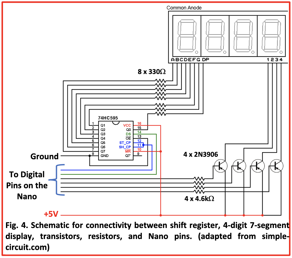
We wired the 7-segment display according to the following diagram:
 After we finished building the circuit, we were able to display numbers with up to 4 digits. But… what if we want to display larger values, such as the frequency of an IR signal?
Part 4 - Upgrading 7-Segment Display
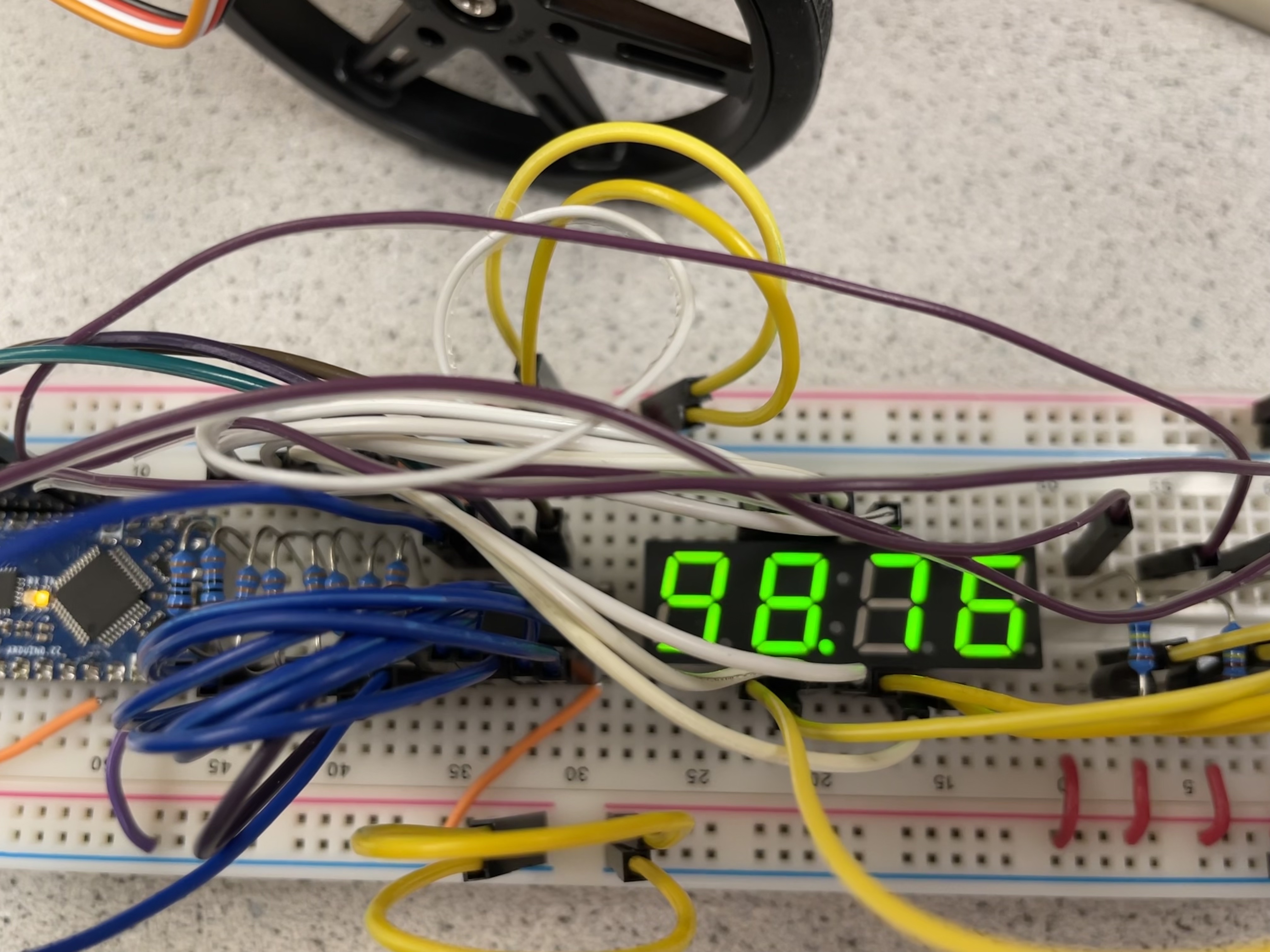
In our code, we modify the number to be displayed if it has greater than 4 digits so that it will display the value in kHz instead of Hz. This involves displaying a decimal point on the 7-segment display. Now, we are able to sucessfully display numbers with more than 4 digits using a decimal point. Here is our display outputting 98765 as 98.76kHz:
Thanks for reading! Come back next week for more~