Tiffany's ECE 3400 webpage
Welcome to my robot-building documentation for Intelligent Physical Systems!
Lab 4: RF Communication, Navigation, and Finalizing Robot
Summary:
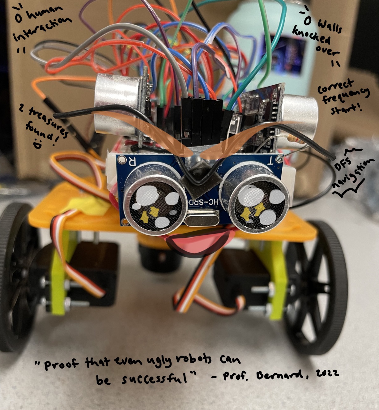
In this lab, we completed the implementation of our robot, including the addition of RF transceivers and a navigation algorithm for the robot to traverse the maze. After an infrared LED is detected by the robot’s phototransistors, its frequency is transmitted to the base station, where it is displayed on the 7-segment display. In addition, we implemented a depth-first-search algorithm as well as PID control for the robot’s navigation and combined all the components from previous labs to produce our final, demo-ready robot.
Task List:
- Implement RF transceivers in robot and base station
- Replace all blocking statements in code
- Implement depth-first-search algorithm
- Implement and tune PID control
- Use servo motor feedback for implementation of turns
- Integrate all components in final robot
- Test robot’s performance in different maze designs
Part 1 - RF Transceivers
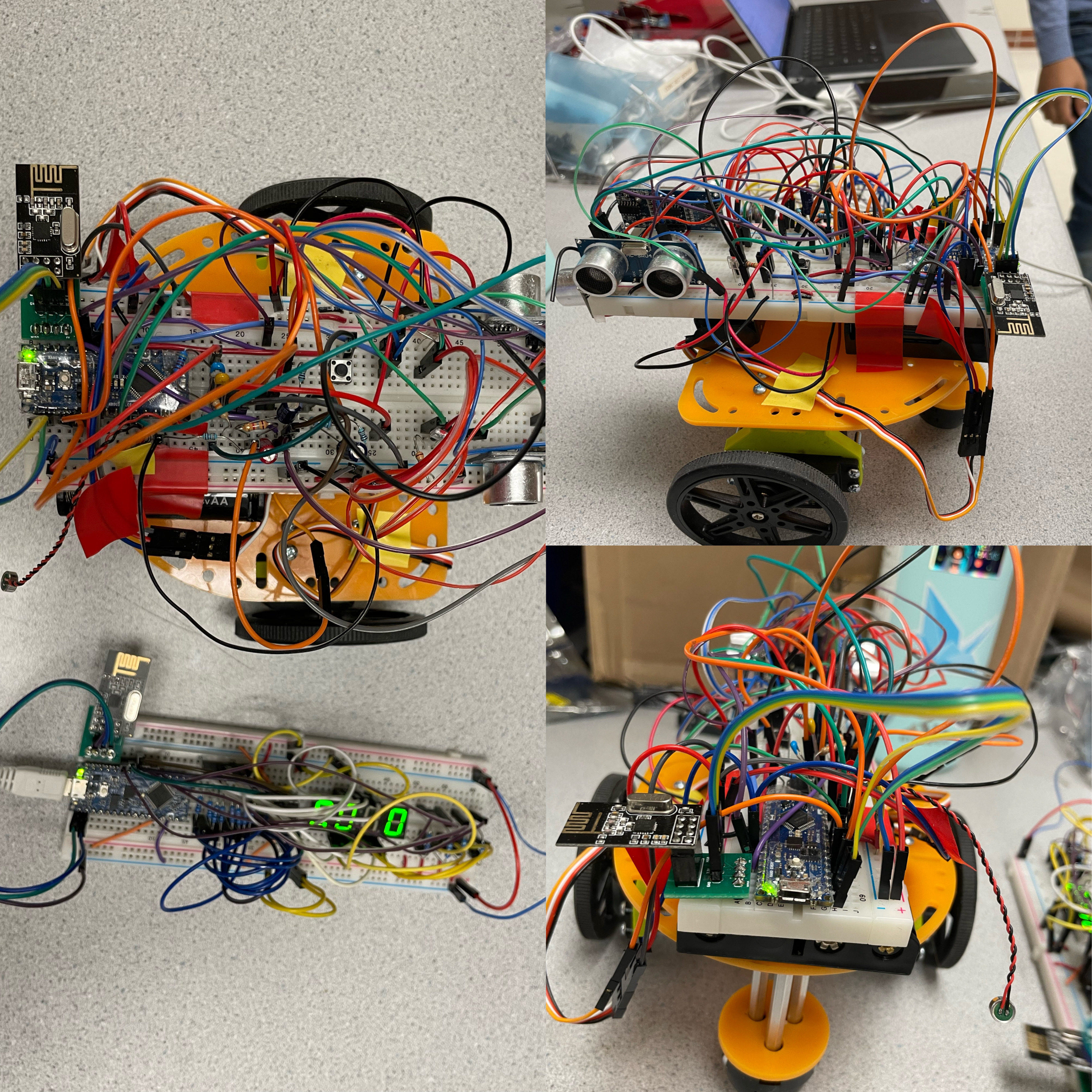
First, we connected an RF transceiver to both the robot and the base station. In both cases, we attached the transceiver to pins D9-D12 of the Arduino and wired the Ground, +3.3V, and SCK pins accordingly. In Arduino, we tested the transmitting and receiving functionality of the transceivers using the RF24 library. We changed the pipe in both files to correspond to a unique number generated using our group number so that our transceivers would not interfere with other groups. Our pipe number was calculated as follows: pipe number = 𝟐(3D+N)+X, where D represents the day of our lab, N represents our team number, and X is either 0 or 1 to represent the transmitter (robot) or the receiver (base station). We tested that the base station was able to accurately receive the transmitted values and then wrote code to transmit values detected by the robot’s phototransistors.
Part 2 - Non-Blocking Code
Some of our code from previous labs included blocking statements, which uses functions such as delay() to wait a specific amount of time. For example, we used this in our turnLeft() and turnRight() functions where we simply timed how long it takes the robot to turn 90 degrees. However, using this method blocks other processes, such as infrared LED detection and PID control, from running while the delay is happening. To fix this problem, we used other methods of timing. In our turning code, we used servo feedback to gauge how much the servos have turned, and we calculated the amount the wheels must turn using a measurement of the circumference of the wheels. In other parts of the code where we wanted to wait for a certain amount of time, we simply called delayMicroseconds() if the desired wait time was short enough. Otherwise, we used a “timer” where we recorded the value of millis() and checked each loop to see if the amount of time elapsed has reached the length of time we want to wait for.
Part 3 - FFT & Override Button
As implemented in Lab 3, the robot will start navigation of the maze once it detects a specified frequency of 440 Hz which is embedded in the starting tune. Using the code from Lab 3, we simply modified it to detect a frequency of 440 Hz. In our main code, we had the robot continuously listen for frequencies until it detects 440 Hz, in which case it will continue and begin navigation. We also implemented the override button in the same way, which acts as a backup start trigger in case the robot does not start correctly.
Part 4 - Navigation
We used a depth-first-search algorithm to navigate the maze with the goal being for the robot to explore every square of the maze rather efficiently. Basically, the robot first reads from its the ultarsonic sensors on the front, left, and right side to determine where a wall is present and which squares it can move to. If the robot can move forwards, it will do so. Otherwise, it will prioritize turning right, and then turning left. If there is nowhere left to go, the robot will backtrack to the last unexplored square. This algorithm requires that we keep track of a list of Frontiers, which are squares where the robot can but has not yet visited, and a list of Visited, which are squares that have already been visited. We represented squares in the maze using a tuple data type, where each tuple contains the [x,y] coordinate of the robot. Here is a map of the entire map represented as tuples:
[0,4]  [1,4]  [2,4]  [3,4]  [4,4]
[0,3]  [1,3]  [2,3]  [3,3]  [4,3]
[0,2]  [1,2]  [2,2]  [3,2]  [4,2]
[0,1]  [1,1]  [2,1]  [3,1]  [4,1]
[0,0]  [1,0]  [2,0]  [3,0]  [4,0]
In the final demo, the robot will start at [4,0] facing North. In order to keep track of the robot’s relative position in the map, we kept track of the orientation of the robot, or which cardinal direction it is facing at all times. Whenever the robot makes a turn, we update this directionality so that it the robot can correctly know its position and relation to other squares on the map. To account for possible malfunctions in the ultrasonic sensors, servo motors, or PID control, we also implemented a backup “right hand” algorithm. If the Frontiers list is empty, meaning the robot has nowhere else to go, but it has not yet found 2 treasures, the robot will simply travel along the right wall and continue to search for treasures.
Part 5 - PID Control and Servo Movement
Even though we are using servo feedback when making turns, sometimes a turn will stop short or turn too far and leave the robot at an angle less than or greater than 90 degrees. When this happens, we want to correct its position as quicly as possible so that it does not get off course and jeopardize the navigation algorithm. Using PID, we use the ultrasonic measurements from the left and right side of the robot to ensure that it moves parallel to the walls. We defined an “error” value as the left US distance - right US distance with the goal being to achieve an error of zero. We then simply tuned the P, I, and D parameters so that the robot converges to the desired path quickly without overshooting and oscillating too much. We also implemented PID on a single wall, meaning that when the robot only senses a wall to its right or left, it will angle itself to move parallel to that one wall at a fixed distance. Here you can see our PID controll at work, correcting our robot whenever its orientation becomes skewed.
We noticed that our robot sometimes got lost while doing DFS when it was moving forward. This is because the feedback from the servo motors is noisy, even after being filtered, and this adds up over time. When the robot has to move two or more squares foward, it might not move enough distance or move too far, causing it to be thrown off course. We observed this issue many times where the robot goes forward a small amount but thinks that it has already moved to the next square. This would throw off the entire DFS algorithm since it would add an extra square where there isn’t one on the map. To solve this issue, we used the front ultrasonic sensor when moving forward. We measured the distance the sensor would be from the wall when the robot is 1, 2, and 3 squares away from the wall, since the maximum length of a path in the maze is 3 squares. Then, we move the robot closer by 1 square and stop when the front US sensor reads the corresponding distance. We found that this method is more reliable and allows our robot to navigate accurately.
Part 6 - Frequency Measurement & Display
As the robot navigates through the maze, it is concurrently detecting treasures using all 3 onboard phototransistors. We do this by looping through each phosotransistor in our code, and if a treasure is detected, we conduct some checks before sending its frequency to the base station. First, we ensure that the detected frequency is within the valid range of 1kHz to 12kHz. Then, we take additional readings to make sure that we are detecting an accurate frequency, as sometimes the phototransistors will read a very high or very low value when first detecting a treasure. Lastly, we only want to send a frequency that is different from a previously detected frequency, so we make sure that this is the case. We then send the frequency value to the base station, where it will be displayed until the next frequency is detected. After two distinct frequencies are detected, the robot stops navigation and blinks its onboard LED. Here is a video demonstrating our treasure detection system working:
Part 7 - Final Demo
For the final demo, we combined all the aforementioned components into one main file and uploaded it onto the Arduino. We spent most of the entire week leading up to the demo in the lab to finish and fine-tune our robot. We ran into some unexpected bugs, including the ones mentioned earlier, which we had to think of creative solutions to overcome. We noticed that as the batteries on the robot drained, the servo feedback values would change, causing the robot to turn less than before. Thus, we tried implementing a filter on the feedback readings, and we also made sure to change to new batteries when we were tuning the turn() functions and also before our actual demo. When combining all our files, we had to make sure our setup() functions were called in the correct order so that all the timer values we use are initialized with the correct values, allowing our sensors to work properly. After many stressful nights, our demo was a success :’) Here is a video of our robot in a test maze that we designed:
Thanks for reading! I hoep you enjoyed watching the evolution of our robot~