Go To:
Home Page
Lab 4: Radio Communication and Map Drawing
The objectives of Lab 4 were as follows:
Radio Communication
Use the FPGA to draw a full maze on a VGA monitor
*Update the maze with information received from the radio.
Radio Team:
Team Members:
Logan
Trisha
*Francis
Materials Used:
2 Nordic nRF24L01+ transceivers
2 Arduino Unos (one must be shared with the other sub-team)
2 USB A/B cables
2 radio breakout boards with headers
Goal: The goal of the radio team is to accurately transfer crucial data from the arduino that will be on the board to the base station arduino that is connected to the FPGA. In addition to the two Arduino Unos, we used two Nordic nRF24L01+ transceivers to send and receive data packages that we created.
Setting Up & Example Sketch The first step was to download the RF24 Arduino library and open the example start sketch. The example sketch gave us good framework that showed us how to set the correct channels and roles (sender or receiver) to our Arduinos. We changed the the identifier numbers for the two pipes according to our team. (8,9). Once we finished setting up all the necessary parameters, we executed the example code. This allowed us to send packages from one Arduino to the other and back. This example code was setup to send and receive current time to calculate time it takes for package to send.
Video of us sending and receiving time data:
Video of us sending packets:
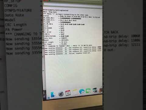
*Note: To send data, user must type T in terminal to signify transmitter role (this will be taken out when placed on Arduino for continuous transmission)
Sending Maze Once we ensured that our Arduino Unos were able to communicate with each other, we started changing the message so that we can sending maze related data. Instead of sending the entire maze every single time (seen in video below), we opted to send 16 bits (2 bytes) of data encoded with vital information about the robot, its position, walls, and the type of treasure present. We had to use an int (2 bytes) instead of a char (1 byte) because we needed 11 bits to transfer all our desired data.
The bits are organized as follows:
| / | / | / | / | / | X1 | X0 | Y2 | Y1 | Y0 | W3 | W2 | W1 | W0 | T1 | T0 |
The two bits for X will hold the X position of the robot (0, 1, 2, 3).
The three bits for Y will hold the Y position of the robot (0, 1, 2, 3, 4).
The four bits for W will hold the walls position relative to current X,Y location and true north.
NSEW
1000 -> Wall on true north
0100 -> Wall on true south
0010 -> Wall on true east
0001 -> Wall on true west
1010 -> Wall on true north and true east
….
*Note: not all bit combination on Y bits are used
By encoding a 2 byte data package, we save the hassle and time sending the entire maze. The two bytes of data sends sufficient information to the base station Arduino to be mapped on the screen. The coding of these bits are relatively simple. For instance: if we wanted to encode x cordinate as 2 (b10), we simply set x as 2 and bit shift left by 9.
Here is a snippet of the code that does the bit shift
 // Ping out role.  Repeatedly send the maze data
      //
      unsigned int message = 0;
      unsigned int return_message = 0;
      int walls = 0;
      int x = 2;
      int y = 2;
      int treasure = 0;

      //to update new location of robot
     //putting numbers to appropriate bits
     x = x << 9;
     y = y << 6;
     walls = walls << 2;
     treasure = treasure <<0;

    message = x + y + treasure + walls;
Once the data is sent and received, the data (int) is printed on the screen in both the sender and receiver for debugging. (See video below)
Sending Maze Video:
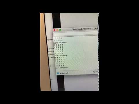
Sending 2 Bytes of encoded Data Video
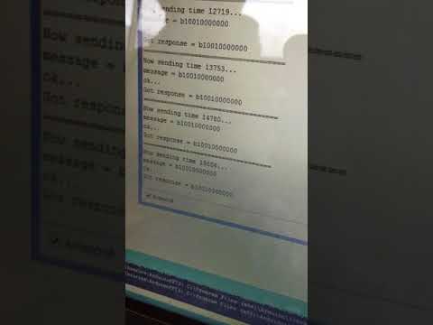
The last thing we tested was that the radio worked at different distances as seen in the following video:

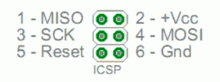
SPI Communication:
Once we completed the maze data transfer between the two Arduinos, we must now prepare the data to be sent to the FPGA via SPI protocol. The SPI protocol requires the four following lines:
* MOSI - Data going from the master to the slave
* MISO - Data going from the slave to the master
* SCK - When the clock toggles, both the master and the slave sample the next bit
* SS or CS - Selects a particular slave to go “active”
Since we made the base station Arduino as the master node, we will use the MOSI line (Master out slave in) to transmit data from base station to the FPGA. Given the SPI functions in the Arduino standard library, transmitting data via SPI is relatively easy. As seen below, in the five lines of code, we are able to transfer the 2 byte data to the FPGA.
SPI.endTransaction(); //to ensure that no transactions are currently occurring

//Set up and begin our data transfer

// 7000000 => the clock rate for data transfer

//MSBFIRST => Most significant bit transferred first

//SPI_MODE0 => bit encoded on falling edge, receive on rising edge of clock

  SPI.beginTransaction(SPISettings(7000000,MSBFIRST,SPI_MODE0));
  SPI.transfer(got_message); // actually transfer message
  SPI.endTransaction(); //end SPI transfer to open channel for others
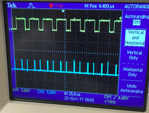
To debug and test, we probed the output of the MOSI line and CLK line of the base station to see the output of the base station Arduino. As seen in the figure below, the yellow is our transaction packet (sending all 1’s), and the blue is our clock cycle. We are sending the data via MOSI line on the rising edge of the clock.
Graphics Team:
Team Members:
Paige
Yonghun
*Jimmy
Materials Used:
FPGA
1 Arduino Uno (shared with the other sub-team)
1 VGA cable
1 VGA connector
1 VGA switch
Various resistors (for voltage divider)
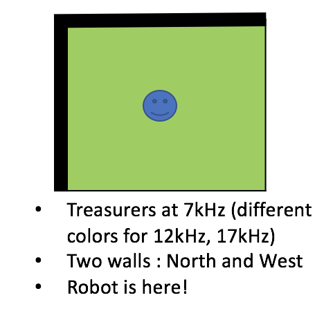
Goal : Create Verilog modules that represents the VGA screen in 4 by 5 grid arrays, assign memory block for each grid, and paint it with different colors based on the travel history and the current location of the robot. The data transmission protocol is set between the base-station Arduino and FPGA. The communication is then tested by sending out the information about the location of the robot from Arduino and representing the corresponding change in location on the grid array through VGA screen.
While we do not know where the walls and treasurers are, we already know its backbone. The maze consists of roughly equal size of rectangular grids (Total 4 rows x 5 columns). We use this information to divide the VGA screen monitor into 4 by 5 grids, each of which will represent information about the wall location, treasurer frequency, and the presence of robot in its path.
*Note : The robot will traverse the middle of the grid, not the edges.
For the laboratory 4, each grid is painted with a single color. For our final competition, we will use the information packet from Arduino to update the information on each grid accordingly by painting edges with black for walls and the main part with various colors corresponding to different frequencies of the treasurer.
However, the VGA driver still paint the screen by each pixel, and so we still need to assign a specific color to each pixel. Therefore, we need a sort of a lookup table that tells us in which grid the pixel of interest is located. For this purpose, we created a separate module–a series of if-blocks that assign grid coordinate in (x,y) to each pixel. This is very similar to the sine wave lookup table we created in laboratory 3.
//Module takes in pixel inputs from VGA driver
//returns value of grid where pixels reside
module MEMORY_GRID(
//// I/O ////
	input clk,
	input [9:0] PIXEL_X,
	input [9:0] PIXEL_Y,
	output reg [3:0] GRID_X,
	output reg [3:0] GRID_Y
	);

always @ (posedge clk)
  begin
  if (PIXEL_X <= 160) begin
	GRID_X <= 0;
  end
  else if (PIXEL_X <= 320) begin
	GRID_X <= 1;
  end
//.............. The rest of GRID_X assignment

  if (PIXEL_Y <= 96) begin
	GRID_Y <= 0;
  end
  else if (PIXEL_Y <= 192) begin
	GRID_Y <= 1;
  end
//.............. The rest of GRID_Y assignment
*Note: For speed and efficiency, we first designed this module to create a 2-D array that holds the grid coordinates for all of each pixel (array of 640 by 480). But, in terms of memory usage, this is antithesis of being efficient, as FPGA cannot even compile because it cannot handle this gigantic memory block!
We initialized the color for each grid, and added these simple lines of code that wires this grid color to VGA driver.
always @ (posedge CLOCK_25) begin
	pixel_state <= grid_color[GRID_X][GRID_Y];
end
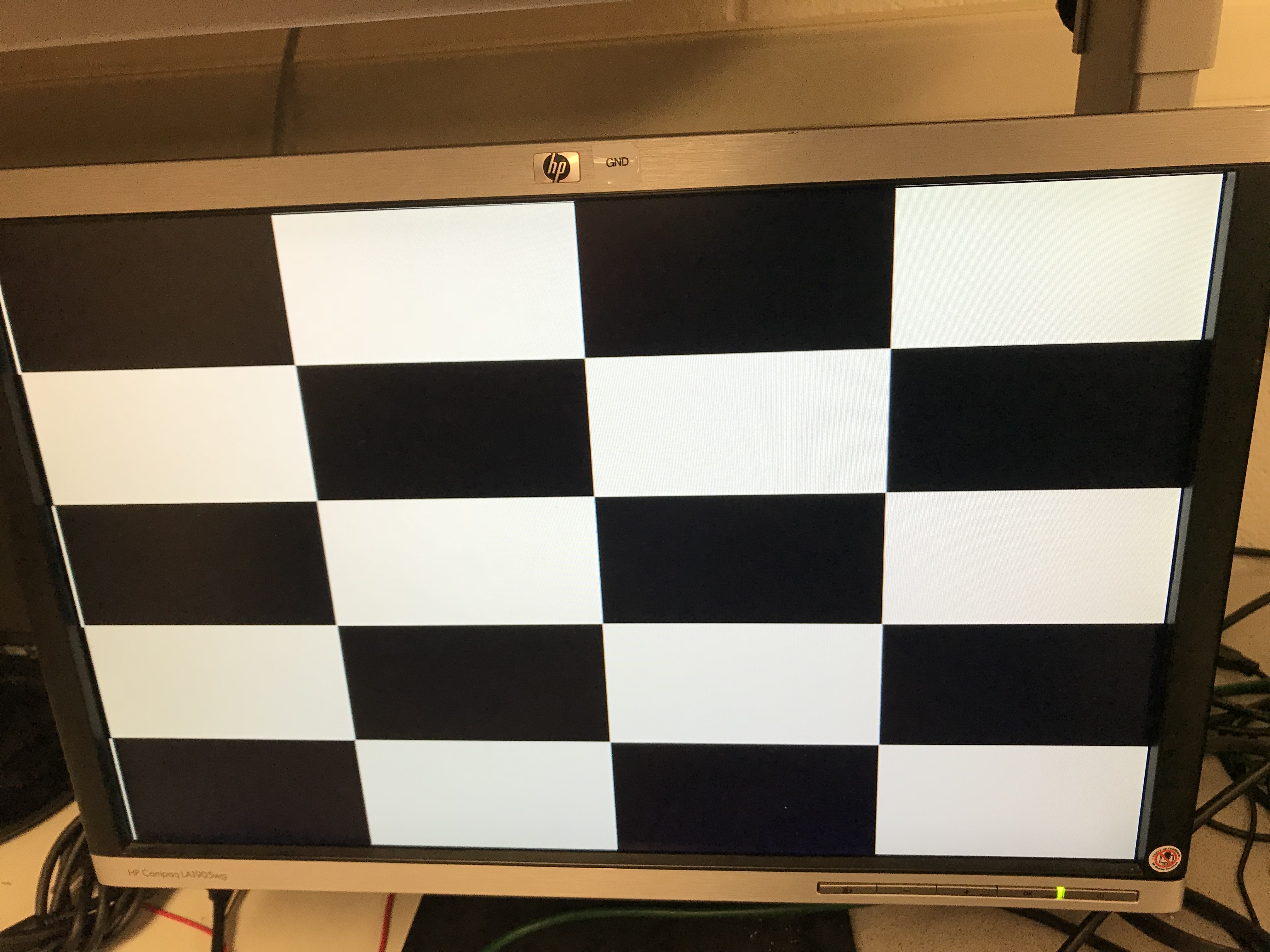
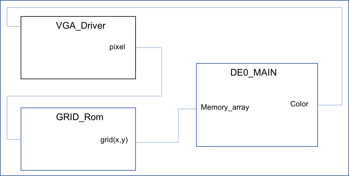
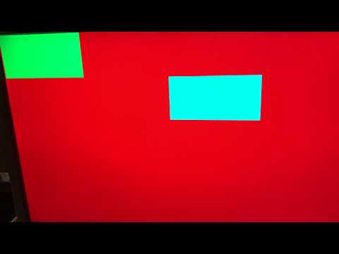
Here’s the full 4 by 5 grid displayed on the VGA screen. We also put a simple diagram to help understand the interaction between the modules.
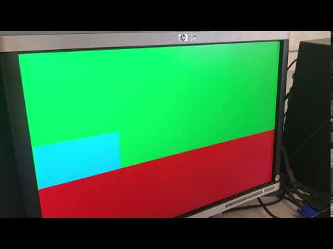
We then created a memory register of 4 by 5 array to store the color value. The grid arrays should indicate where the robot is currently at, and what sites have or have not been visited. We decided to paint all the arrays in red for initialization, blue for the grid the robot is currently at, and green for the grids that have been previously visited. We accomplish this by the following code:
//// I/O ////
wire [3:0] X_CURR;    // Current position x
wire [4:0] Y_CURR;    // Current position y
reg [3:0] X_PREV;     // Previous position x
reg [4:0] Y_PREV;     // Previous position y

always @ (posedge CLOCK_25 or posedge reset)  begin
	if (reset == 1) begin
	// initialize all necessary values
	grid_color[0][0] = red;
	grid_color[0][1] = red;
	//..........Grid array color initialization...........//
	X_PREV = -1;
	end
	else begin
		if (!(X_CURR == X_PREV && Y_CURR == Y_PREV)) begin
		// robot has moved!
		grid_color[X_PREV][Y_PREV] = green; //Have been visited
		grid_color[X_CURR][Y_CURR] = teal;  //Current position
		X_PREV = X_CURR;
		Y_PREV = Y_CURR;
		end
		else begin  //robot has not moved
		X_PREV = X_PREV;
		Y_PREV = Y_PREV;
	    end
	end
end
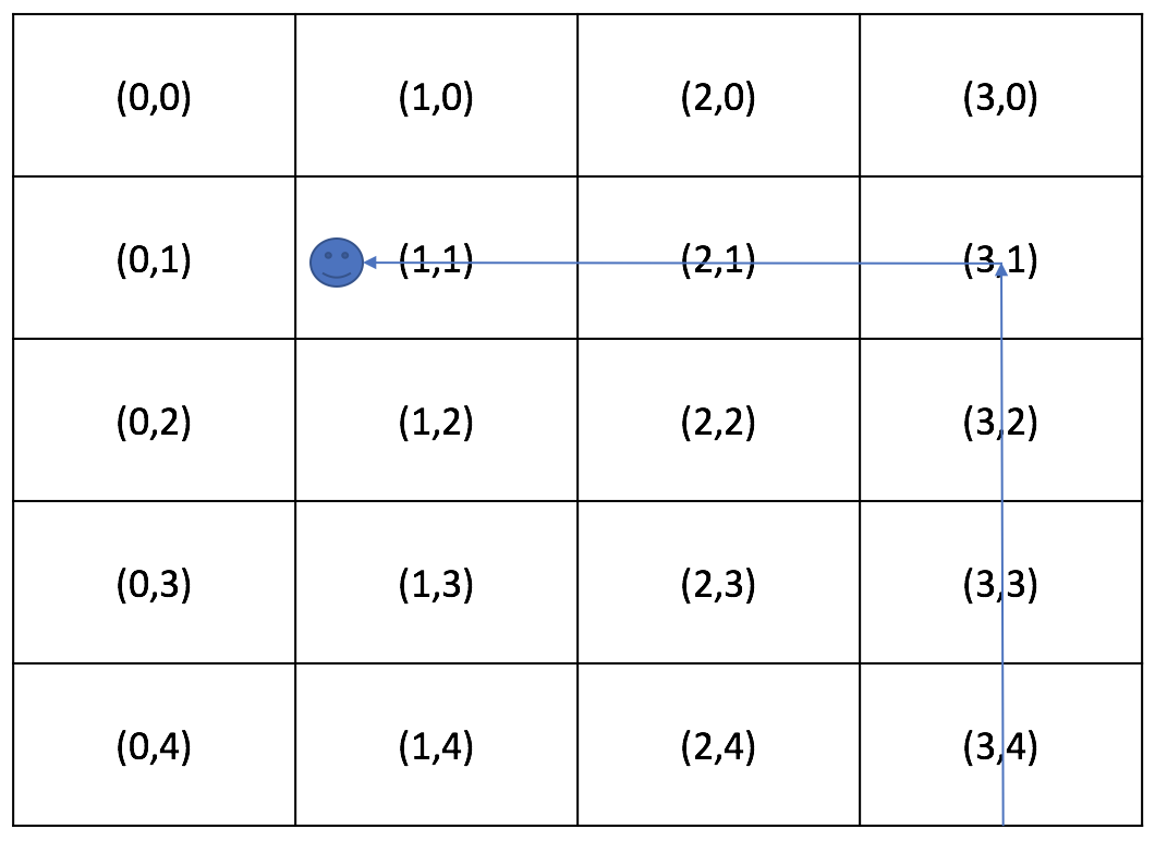
In order to check that this implementation works, we created a simple test case, by which the robot traverses from right to left, top to bottom:
VIDEO :
The next goal is to build a communication path between the base-station Arduino and FPGA. As explained in the Radio section, we decided to use the serial communication, and each data packet consist of 12-bit information (total 16-bits, the rest of 4 bits in 0’s), and because each bit comes in series, the key is to use the shift register to build a complete 12-bit data packet for each transmission and parse them into information about (x,y) coordinate, walls, and treasurers. Several assumptions/considerations we have made here:
- The transmission protocol we use here is a gross simplification of the ordinary Serial Peripheral Interface (SPI). There is only one Slave (no SS). And the Slave (FPGA) only receives signal (no MISO). Finally, we do not send acknowledgement signal to Master.
- SCLK (serial clock, the rate at which each bit of MOSI arrives at FPGA) is slower than the Master’s clock (SCLK at 4MHz, FPGA at 25MHz).
- Data transmission happens whenever the robot traverses to a new grid. This takes place in the order of seconds, while the actual data transmission happens in the order of less than microseconds.
We created a separate module for SPI Communication.
module SPI_COMMUNICATION(clk, sclk, bit_in, x, y);
// I/O //
//...ordinary I/Os omitted for the sake of brevity.. //

input clk;  //internal 25 MHz clock
input sclk;  // clock to communicate with arduino
input bit_in;

output reg [1:0] x; // Current X grid coordinate
output reg [2:0] y; // Current Y grid coordinate
reg [7:0] v; // Shift-register

always @ (negedge sclk) begin
    counter <= counter + 1;
    v = {v[6:0],bit_in}; // Shift-registering each bit input
    if (counter == 4'd8) begin
    done = 1;  // 8bit data packets are received
    counter = 0;
    else begin
    done = 0;
    end
end

always @ (posedge clk) begin
	if (done == 1) begin  // When a full 8-bits data packet is built
		x = v[4:3]; // Parse data into (x,y) coordinate
		y = v[2:0];
	end
	else begin
		x = x;
		y = y;
	end
end

endmodule
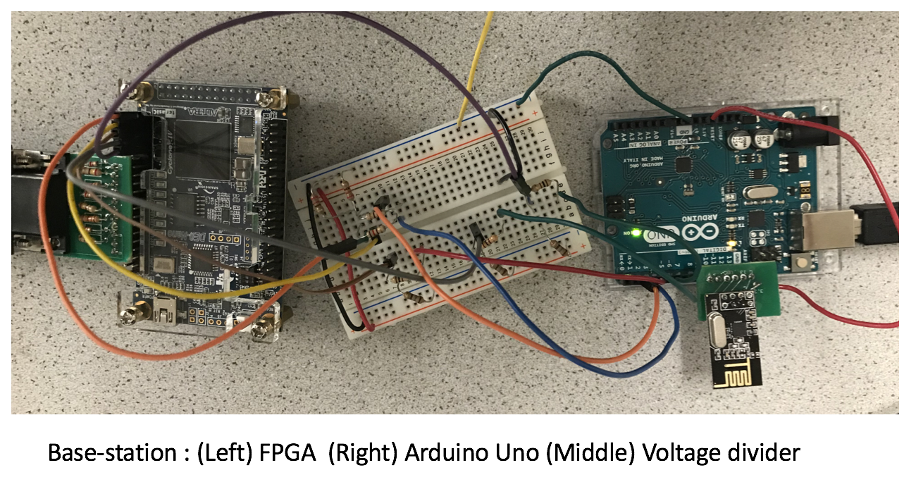
Arduino’s digital output signal is 5V at HIGH, while FPGA’s GPIO pin accepts the signal at 3.3V. In order to match the voltage output value, we used a simple voltage divider to connect the SCLK and MOSI from the Arduino to FPGA GPIO pins (220 ohms for FPGA output & 110 ohms).
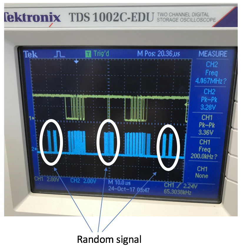
However, the serial communication did not work. We attribute this failure to unwanted data packets randomly generated by the Arduino at the higher frequency than the regular SCLK (screenshot of the oscilloscope below). Until we can improve our code to filter out unwanted data packets, we decided to temporarily switch to parallel communication.
For simplicity, we assigned five Arduino digital pins to FPGA GPIO pins, each pin conveying each bit of the total five bits data packet. We designated two bits to x-grid coordinate, and three bits to y-grid coordinate. Each pin connection goes through the voltage divider to make sure that FPGA receives a maximum of 3.3V (total 5 voltage dividers).
Here’s the module code for the parallel communication. The module gives an output of the current location of the robot in grid (x,y) coordinate. Our main program already has a full implementation of changing grid color based on the traveling history of the robot, and all we have to do is to wire this module.
*NOTE: At first, we ran the module at the FPGA’s 25MHz frequency. However, at this frequency, the grids adjacent to the one the robot is currently on were also colored unexpectedly. We believe this happens because the data transmission time is slower than the clock frequency and the signal is not properly debounced. After we changed the frequency to 1Hz, this problem was immediately resolved!
module Parallel_COMMUNICATION(led, clk, sclk, bit_in_one, bit_in_two, bit_in_three, bit_in_four, bit_in_five, x, y);

output reg[4:0] led;

// I/O //
//...ordinary I/Os omitted for the sake of brevity.. //

input bit_in_one;
//...up to bit_in_five.. //

reg [1:0] xtemp;
reg [2:0] ytemp;

always @ (posedge clk) begin
	if (counter == 0) begin
		counter = 25000000;  //Change the clock frequency to 1Hz
		xtemp = {bit_in_one, bit_in_two}; //Concatenate first and second bits
		ytemp = {bit_in_three, bit_in_four, bit_in_five}; //Concatenate third, fourth, and fifth bits
		if (xtemp != x || ytemp != y) begin //Position is changed
			x = xtemp;
			y = ytemp;
		end
		else begin //Position unchanged
			x = x;
			y = y;
		end
	end
	else begin
		counter = counter - 1;
	end
end

endmodule
For the Arduino code, we simply turned digital pins ON (bit 1) or OFF (bit 0), while making sure each digital pin is correctly connected to the FPGA’s (x,y) input (two pins for x-coordinate, three pins for y-coordinate). For example, digital pin 3,4,5,6,7 = (1,1,0,0,1) represents the grid point (x,y) = (3,1). We gave several seconds of delay between changing the output values.
Here is a segment of our Arduino Parallel code:
  //2,1
  delay(5000);
  digitalWrite(2, HIGH);   // turn the LED on (HIGH is the voltage level)
  digitalWrite(3, LOW);    // turn the LED off by making the voltage LOW
  digitalWrite(4, LOW);
  digitalWrite(5, LOW);
  digitalWrite(6, HIGH);
  delay(2000);
And finally, we demonstrate that the maze array is indeed updated only upon receiving the signal from the Arduino. MOSI data packet specifies where the robot is currently at, and we color the grid accordingly.
*NOTE: In this video, the robot seems to ‘teleport’ through the maze array, because the updated locations from the Master do not simulate the actual robot’s motion.
VIDEO :
Go To:
Home Page