AutoCAD for 2D Design: Tutorial and Chassis Example
The goal of this tutorial is to supplement the ECE 3400 autoCAD tutorial and example the TAs made. I had no experience with autoCAD at all when I started this class, so I will try to go into greater detail on some things I learned on my own and point out some of the more heuristic tricks I figured out in my process.
Downloading and Opening AutoCAD
First things first, you need to download autoCAD from autodesk, which is free for Cornell students.
Open up autoCAD and click on the acad.dwt selection. Note that autoCAD automatically saves these files as .dwg extension file, a file that can also be opened on SolidWorks, which is program that prints to the laser cutter. If you want to create a 3D image in order to print it to a 3D printer, you will need to export it as a .stl file.
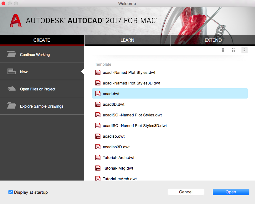
You should see the default opening screen.
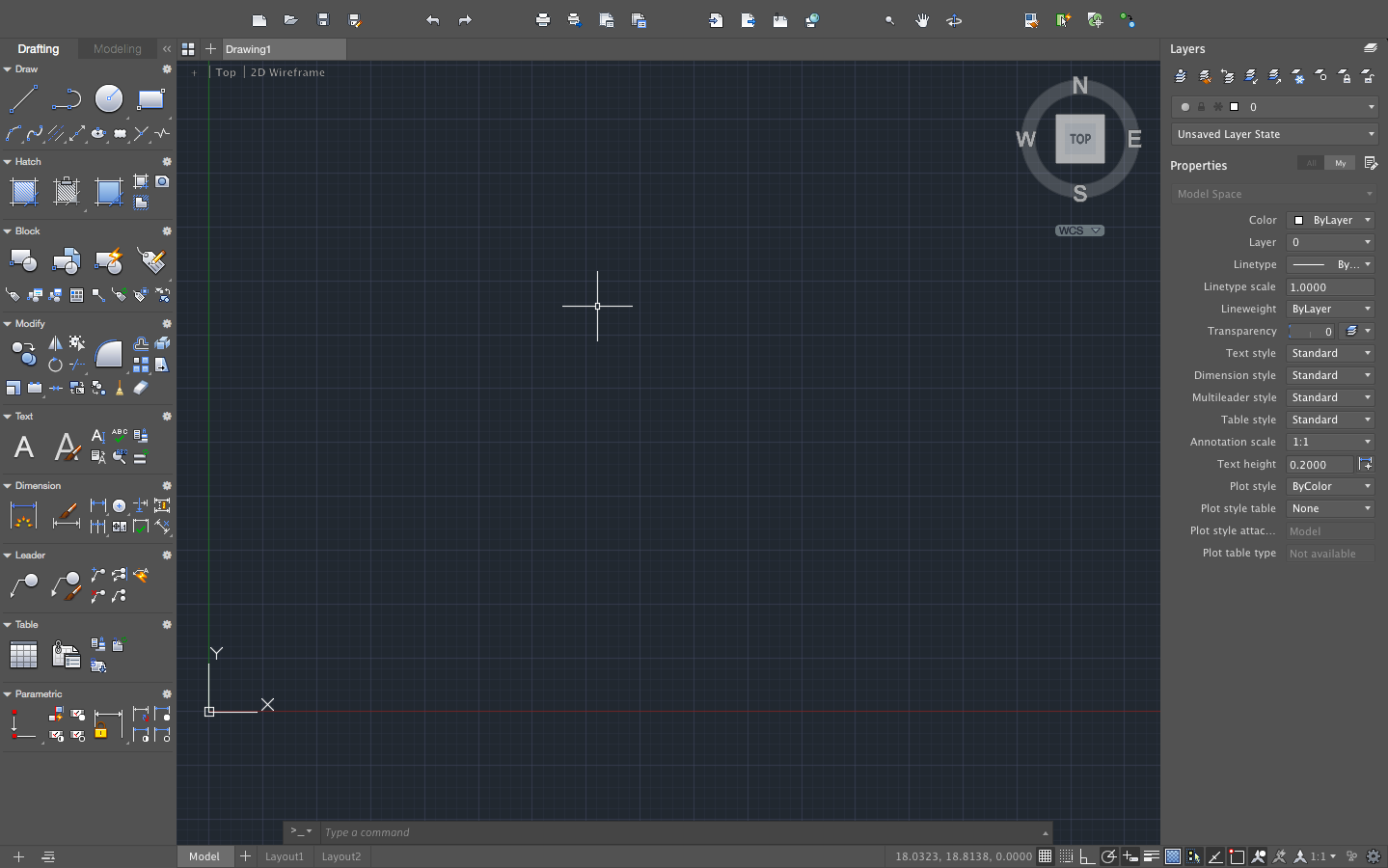
Note that my version looks slightly different from the TAs (and may look different from yours, depending on the version you download), but the basic components are the same and most of the icons are labelled intuitively.
Using AutoCAD
AutoCAD has a bunch of features that I couldn’t possibly tell you all about, so most of what you will know about autoCAD you will learn from playing around with the buttons and googling. If you think you can do it in autoCAD, you probably can and somebody has probably already asked the same question on the internet.
Useful Tips
Before you try anything fancy, you need to know that the ESC key is your best friend. Locate the ESC key on your keyboard. Remember where it is; love it; cherish it. Whenever a command isn’t executing how you think it should be, or you accidentally type in a command you don’t want, or whenever something funky is going on and you don’t know how you got there, press the ESC key.
Your next best friend is the undo command, Ctrl+Z. If ESC didn’t fix your problem, press Ctrl+Z until you return to a place you recognize.
Many people also prefer to use an actual mouse instead of the trackpad for a laptop since it makes things easer to click and drag as well as allows you to zoom into the image relatively easily. This is entirely up to your preferences however.
Snapping
Snapping essentially shows and “prefers” certain points that exist in your drawing over others so that when you are drawing a line, for example, it will “snap” to these points. These points are usually relative elements that already exist in your drawing, like endpoints or midpoints. For example, in the image below, the green triangle indicates the midpoint of the given line segment, so now I can draw another line with one point exactly in the center of the first line segment.

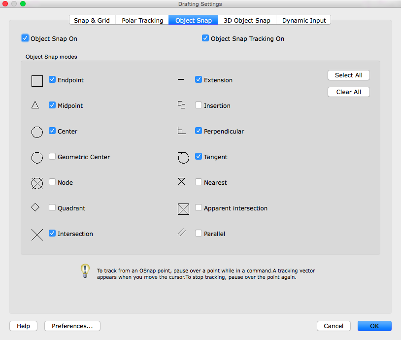
You can turn on/off snapping at the bottom of the screen. You can edit your snapping preferences by holding down the control button on your keyboard while clicking on the snapping icon.
You will get the following screen. The Object Snap tab will allow you to determine what kinds of points will be snapped.
The AutoCAD Command Line
The command line is at the bottom of the screen, but you don’t need to click on it to use it; instead, you can start typing in letters until you get to the command you want and then hit enter. Most commands are labelled rather intuitively and will come up naturally when you start typing them. For example, say you want to draw a line. Start typing “LINE” (note that it doesn’t need to capitalized). As soon as you press “L”, the command for “LINE” should show up since it is so commonly used. Press ENTER and you will then apply the “LINE” command. If you want to specify a length for the line, you can also do so from the command line after choosing a starting point.
The TAs have already made a good list of useful commands on their tutorial. I would also include the UN (units) command. Make sure you are designing in the correct units! Here is a comprehensive list of autodesk’s keyboard shortcuts and commands.
The right column tells you what the command does. The left column tells you the letters you need to type in to execute the command. For example, here are the first few commands that start with the letter “M”.
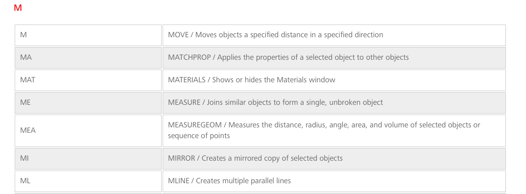
If you want to mirror something across a line, for example, you simply type in “ME” followed by the return/enter key and you will then be prompted to specify the points you want to measure.
Most commands will then walk you through the steps to use it. Many commands also have other ways to specify the necessary parameters. If you press the down key after selecting a command, a list of parameters, if applicable, will appear for you to click on.
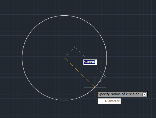
For example, consider that you want to make a circle of diameter 2.75 in. First, type in “C” and hit enter. Pick a starting point.
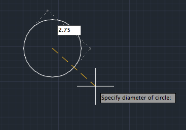
Note that the command is prompting you to specify a radius. You can click on a point on the screen and that would specify the radius, but this is not necessarily accurate since you want a diameter of exactly 2.75 in. You could divide by 2 and type in the result to specify the radius. But you are to lazy to do this. Instead, press the down key and you will see that you can specify the diameter instead.
Coordinates
The coordinate system, by default, is global, i.e. with respect to the big xyz coordinate in the bottom left corner. If you want to make sure you are specifying distances and lengths in a global coordinate frame, use the “#” key before specifying points. If you want to use points in a frame relative the last specified point, use “@“.
Chassis Example
I’m going to walk you through a really quick example by modifying the chassis to laser cut. There was a point when our team wanted to use a line sensor array attached to a mux, so we needed to make a new chassis so that it had the correct placement for screws for the sensor as well as a hole in the bottom for the wires attached to the mux.
First things first, make sure you have taken and recorded all the proper measurements. You may have realized by now that a screw hole a couple millimeters to the left may not fit how you like it.
Secondly, don’t reinvent the wheel. The TAs have given you access to the files they used to create the chassises, wheels, wall sensor mounts, etc you are currently using. You can find and download those files (here). If you want to create a new chassis, for example, I highly recommend looking at their file first. (PSA: you already know their screw holes are the right size, and you can copy and paste elements between files by selecting them and then using the EDIT dropdown menu).
Tutorial
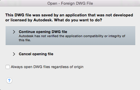
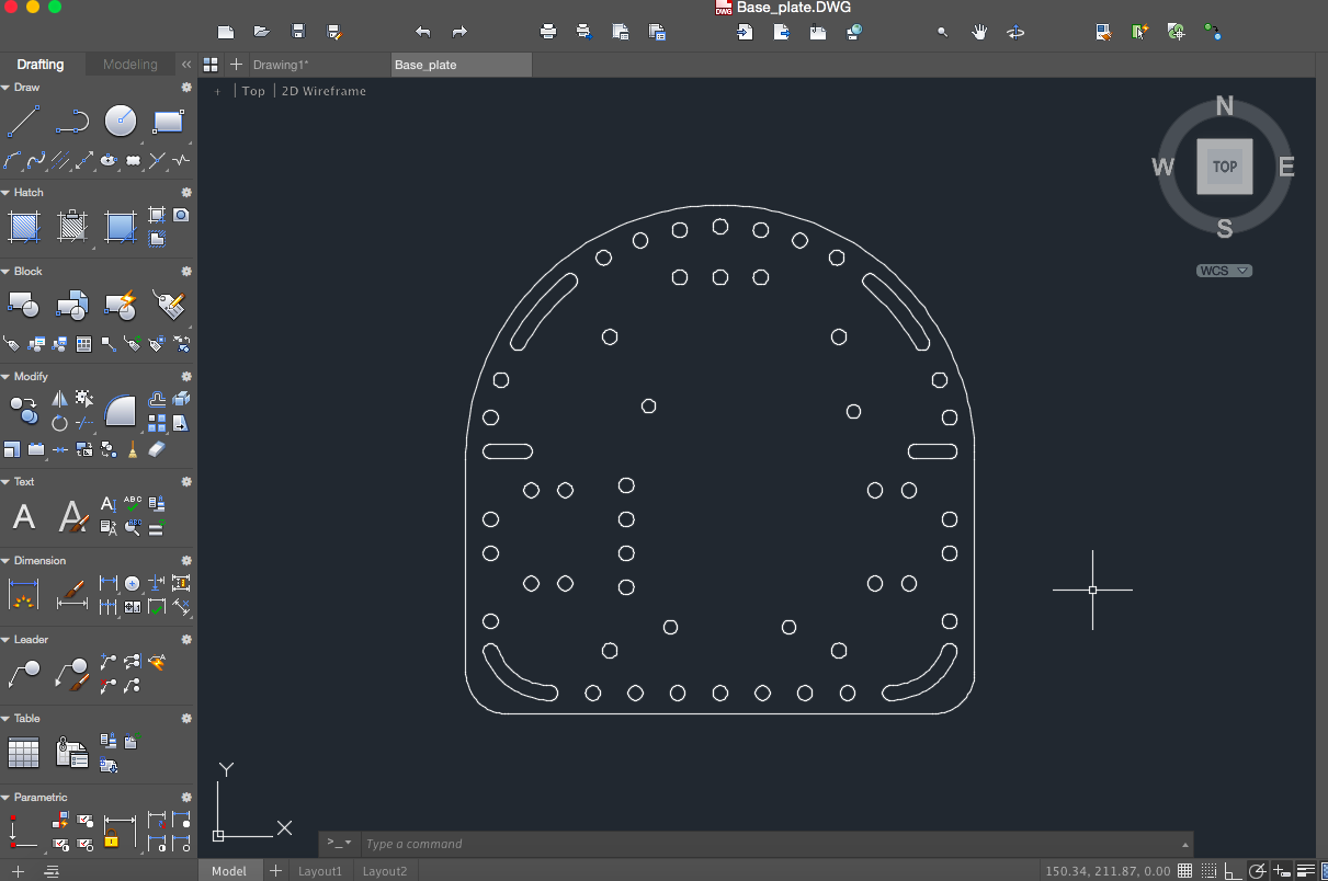
First, make sure that the file you are working on is in the units you want to use. I use millimeters. Open up the Base_plate.dwg file from the collection of files downloaded from the course github. You may get the following warning. Click OK.
Select the elements of the original base plate you care about.
Copy them using the dropdown menu. Move to your new workspace and paste the copied elements.

We want the wheels and the holes for the wires to sit in the center of the chassis in line with the midline of the wheels. In order to make things easier for us, we’re first going to make some guidelines that bisect the chassis at the points we want.
First, draw a line from the center of the top left servo screw hole to the bottom left servo screw hole. If you have snapping on, this is very easy.


Now draw another line from the midpoint of this new line out past the midpoint of the chassis (we don’t care about the exact values of this line, only that it intersects with the middle point we want). This line will be the line along which the screw holes for the line sensor will lie. Now draw another line from the top screw hole to the bottom screw hole in the vertical line that bisects the chassis. The intersection that was just created is the center of the square that will serve as the opening for the line sensor wires. We want to work in that reference frame, so that point will serve as our relative origin.

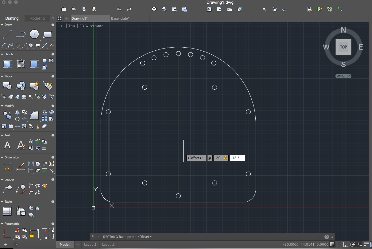
We want a rectangle that is 40mm by 25mm centered at intersection point we just created. This means that we want the bottom left corner of our rectangle to be at the point (-20, -12.5) in our new reference frame.
Create this rectangle and specify this point by first typing in “RECT” and enter. Type “FROM”, and select the intersection point. Then type “@-20,-12.5” and enter.
When the command line prompts you for another point, type “@40,25” since the new reference frame is the one you just entered, i.e. the bottom point of the square.
Now the only thing left to add are screw holes. Type in “CO” and enter to copy one of the other screw holes. Select one and choose the center as a reference point.
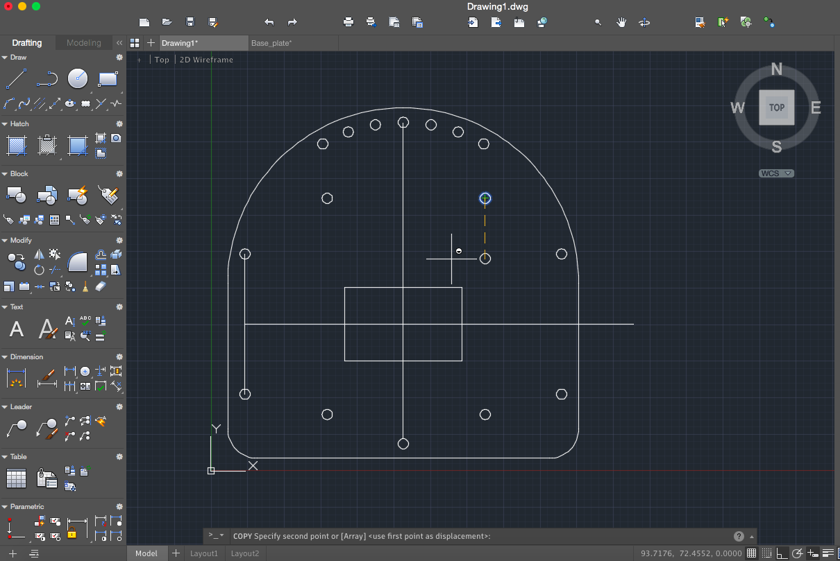
We want two screw holes, each 35mm from the intersection point we created with our guidelines. We are going to do something very similar to what we did earlier. As soon as the command prompts you to specify a second point, type “FROM” and click on the intersection point. Then type “@-35,0” and enter.

You can still place more copies, so type “@70,0” and enter (since we are in the most recently specified point’s coordinate frame). You need to press enter again to complete the COPY command.

Now all you need to do is select all the guidelines we were using and delete them and you’re done!

Go To:
Home Page