Go To:
Home Page
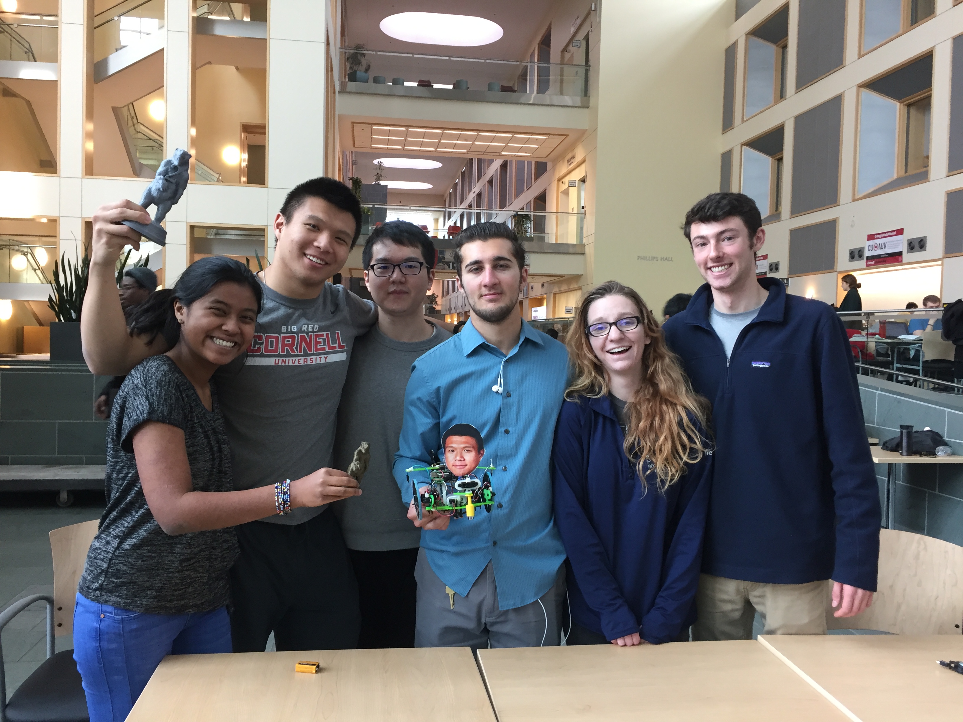
Meet Calvin and the Mutant Mazerunners
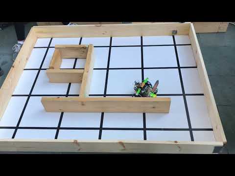
Here’s a video of Calvin taking the second place in the final competition!
A Breakdown of Our Final Design
Breif Overview of Physical Design
Here is a look at Calvin:
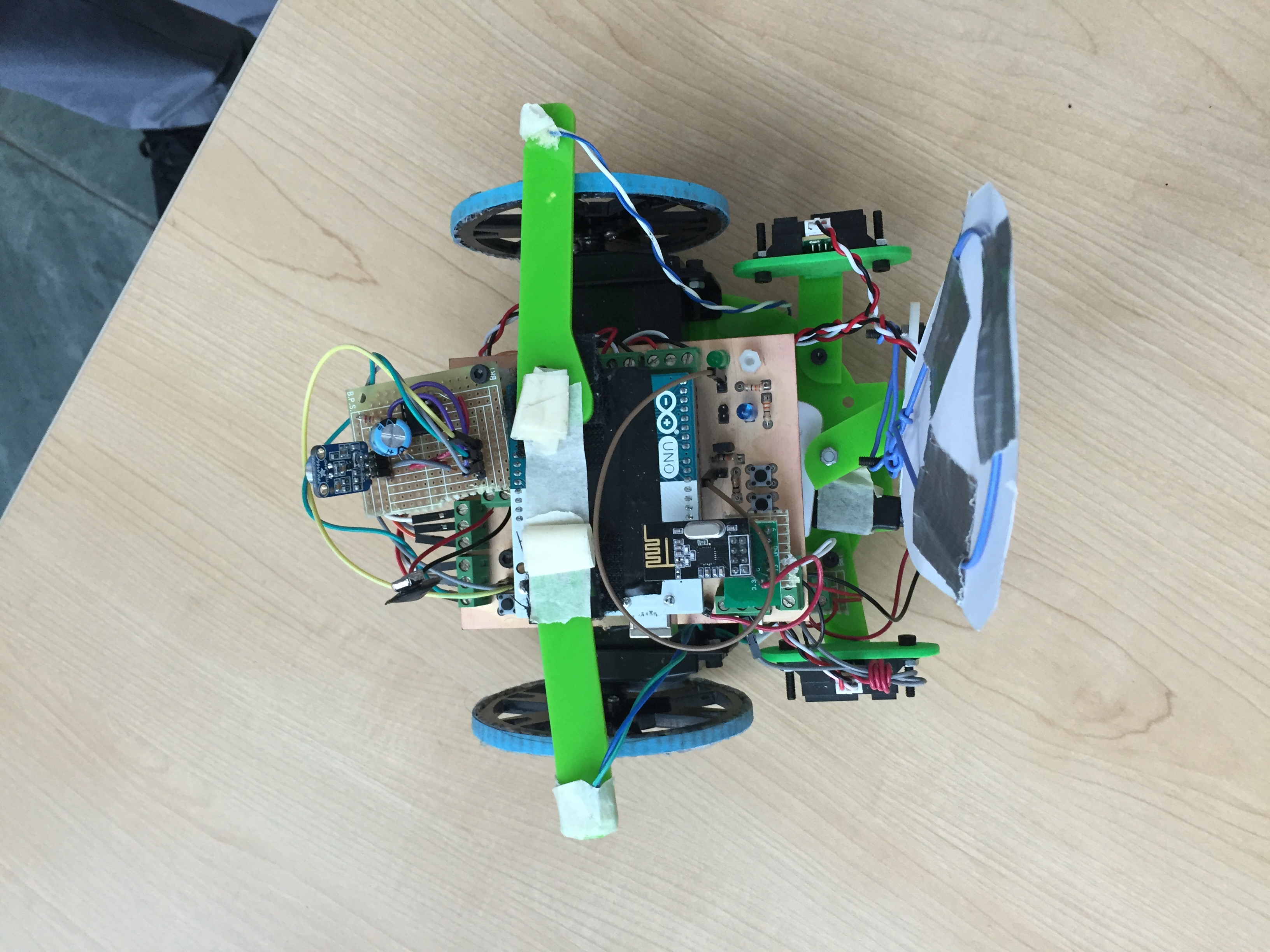
Our robot used many of the parts given to us in lab. To see a complete list of components, go to the Cost and Components page. In order to reduce the amount of physical wires on our robot and optimize our system, we decided to print a PCB. We also printed a chassis using a laser cutter so it would meet our design needs in terms of where the holes were and how the other components would fit together on the chassis. We used two treasure sensors, one above each wheel. We used three line sensors, two for line following and one for intersection detection. We used three wall sensors, one on each side and one on the front. We used a power bank to power the servos and used a 9V battery to power the rest of the system.
Look through our labs and milestones for in-depth details on the physical design
Physical Design Future Improvements to Consider:
- Use a Line Sensor Array (and order a spare just in case)
- Find large and sturdier wheels that stay secure
- Create a slimmer model to reduce risk of robot hitting walls
Wiring Design
Our design emphasis was simplicity. We wanted to minimize the number of active components on our robot while maintaining a robust hardware design. For this reason, we chose to use only two line sensors and a single intersection sensor. We used three additional analog inputs for the microphone and two treasure sensors. These sensors used up all of the analog inputs on our Arduino UNO. We utilized a Schmitt Trigger IC (SN74HC14) for the wall sensors so that they could be configured as digital inputs (Schmitt trigger functionality is explained in Milestone 4). In addition, we added three pushbuttons and two LEDs for debugging/control purposes. Two-pin headers were placed throughout the design so that the battery, LED’s, and pushbuttons could be connected and disconnected at will. This was crucial to the final testing and development as it allowed us to use these pins for other things; when one pin began malfunctioning we were able to easily swap its role. Our wiring diagram is shown below:
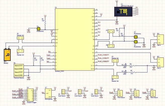
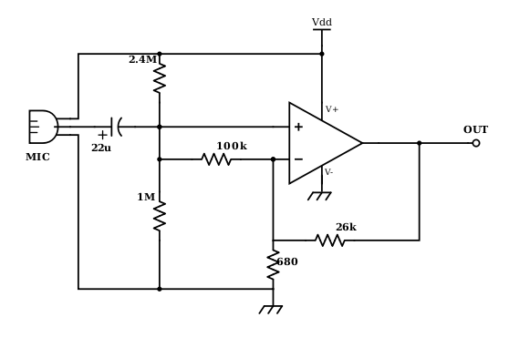
We ended up adding an op-amp circuit to the microphone in order to amplify the signal; its design is explained on the optimization page. The treasure sensors, on the other hand, worked well without amplification. Also, we found that one battery would not be sufficient to power Calvin; we decided to power the servos from a separate battery in order to separate its load and avoid the effects of the servos’ back-EMF coupling onto the supply and interfering with the analog sensors.
PCB Design
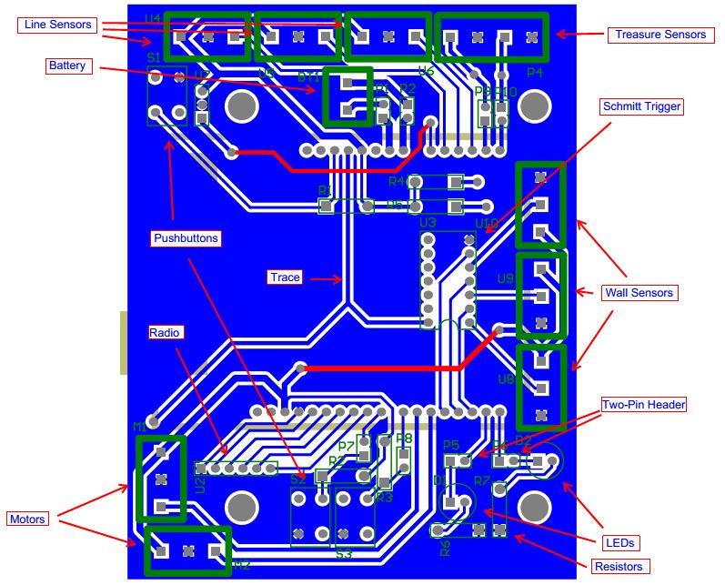
We decided to create a PCB to simplify the mess of wiring on the robot and make the connections more permanent. The detailed design process is explained on the PCB Tutorial page. The final layout is shown below:
| |
|
There are header pins for the Arduino UNO to plug onto, as well as terminal blocks for all of the sensor connections, a socket for the Schmitt Trigger, 3 pushbuttons, 2 LEDs, and various passive components. We recommend using the following image from this website to measure out the hole spacing.
Manufacturability and space were the two primary concerns; we decided to mill the board in the Maker Lab so we needed to be wary of its tolerances and its cost. The copper is expensive per square inch so we wanted the board to be as small as possible while still accommodating all of the necessary components.