Lab 1: Microcontrollers
Materials
For this lab, we will need the following:
Software:
- Arduino IDE (Available Here)
Hardware:
- 1 Arduino Uno
- 1 USB A/B cable
- 1 Continuous rotation servo
- 1 Pushbutton
- 1 LED (we chose a blue LED)
- 1 Potentiometer
- Several resistors (300Ω and kΩ range)
- 1 Solderless breadboard
Arduino Uno and IDE Communication!
Connect Arduino Uno to computer with USB A/B cable, launch Arduino IDE, and pull up the example sketch:
Blink (File -> Examples -> 01.Basics). You should see this:
- pinMode defines a digital pin as INPUT or OUTPUT.
- LED_BUILTIN is a digital pin 13 connected to the on-board LED
- digitalWrite writes HIGH or LOW to a digital pin, turning LED ON or OFF.
Now upload Blink to the board by clicking the rightward arrow beneath the top toolbar. The on-board LED turns ON and OFF for one second each!
Any errors will show up on the IDE and can be solved by either fixing an error in code or adjusting the settings under:
(Tools -> Board, Port) to match your setup. More info about setup can be found at the Arduino Environment Guide.
Blinking an External LED!
Now we will adjust the sketch to blink an external LED.
- Open a new sketch under (File -> New)
- Create the circuit shown here. Note: Resistors are always necessary to avoid overcurrent and breaking the board!
- Use Arduino functions pinMode, digitalWrite, and delay to blink an external LED with 1s intervals. From the sketch setup function, make the following simple modification:
  char LED_PIN = 12;           //Any one of digital pins available
  pinMode(LED_PIN, OUTPUT);    //digital pin 12 configured as OUTPUT
Note: Information about these and all functions can be found on the Arduino Reference Homepage.
Here’s our blinking LED!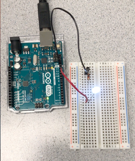
Reading Analog Values via Serial Monitor!
Analog voltage is read by Uno’s analog INPUT only pins; it can be displayed on a built-in feature called the Serial Monitor.
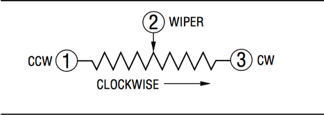
Potentiometer is a variable resistor with three-terminals, which can act as an adjustable voltage divider. As shown below, by turning its knob either counterclock or clockwise, we can change the voltage supply from 5V all the way down to 0V. (Potentiometer 3306F-103 specs)

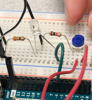
- Wire up the circuit shown here, using a potentiometer and safety resistor.
- Use the built-in functions An_PIN to define an analog pin and Serial.begin(9600) to initialize the serial monitor. Furthermore, in the loop function…
  delay(500);                        //update every half a second
  float ans = analogRead(An_PIN);    //read voltage value from Potentiometer
  ans /= 205.0;                      //analogRead() has a 10-bit ADC (0~1023), so we divide by 205.0 to see the voltage input
  Serial.println(ans);               //print out analog voltage value on the Serial Monitor
3. Upload the sketch, and click the circle button on the upper right-hand corner to start the Serial Monitor
- As we turn the potentiometer knob, we should be able to see the voltage changing!
Controlling LED Brightness Using Analog Output!
Arduino does not have a built-in analog output. Digital output can only either turn LED on or off.
Therefore, we use digital pins that are equipped with pulse width modulation (PWM) to simulate analog output.
PWM rapidly switches ON and OFF, and the average of ON and OFF time represents the analog ouput. The longer the ON time is (higher duty cycle of pulses), the higher the resulting analog voltage is.
Cool Fact: PWM frequency is at approximately 500Hz(reference); the LED turns on and off so fast that human eyes only see a steady brightness!
- Wire up the circuit as we show here. (~ indicates pins with PWM)

- Pick one of PWM capable digital pins (6 here), and use it as a digital OUTPUT.
- Use the builtin function analogWrite for the PWM output
- Use the analog input value at pin A0 to set the duration of ON time for PWM pin 6
  float ans = analogRead(An_PIN);     //analog input pin A0 reads voltage value from Potentiometer, and...
  analogWrite(out_an_pin, ans/4);     //pass it onto PWM digital pin. Duty cycle from 0 (0%) to 255(100%).
                                      //Scale factor of 1/4 needed to map analogRead onto analogWrite
You should be able to control the brightness of the LED by moving the potentiometer, as we have done here!!!
Note: You can also look at your PWM output using an oscilloscope; you should see a square wave at around 490Hz.

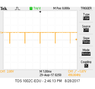
On the right, PWM is maxed out. This is effectively an analog output of 5V!
Controlling a Servo Using Analog Output!
The analog output can also control a Parallax Continuous Rotation Servo
A servo is a special kind of motor which spins with controllable speed and position.
For extra help, see the Arduino Servo Reference Page.
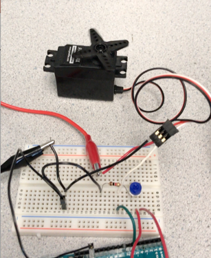
- Wire the circuit as we have shown. We need extra power from a battery!

- Include the Servo.h library using the command: #include Servo.h
- Use Servo.h builtin functions attach and write to control the servo.
attach() connects a digital pin with pwm capability.
write() controls the speed of servo (0: full speed, 90: zero speed, 180: full speed in the other direction). - We can control servo speed using the potentiometer knob!!!
If you need a voltage regulator for your batteries, see our blurb about it on the Related Info Page.
Here is our code for the last part:
#include <Servo.h>

//create servo object, output/input pins
Servo servo;
char servo_dig_out = 6;
char An_PIN = A0;

void setup() {
  Serial.begin(9600);
  servo.attach(servo_dig_out);    //connected to pwm digital pin output
}

void loop() {
  delay(500);                     //need a delay so we don't rewrite output constantly!
  float ans = analogRead(An_PIN);
  ans = (ans / 1024)* 180;        //map analog input range to servo output range
  servo.write(ans);               //servo's speed and direction determined by analog voltage read
}
Take a look at how we control Servo!
Congratulations, you have completed the official lab! Now you can play with your robot…
We wanted to build something simple which could turn in circles.
We first gathered an assortment of materials:
Chassis, screws, nuts, bolts, allen key, 9V battery, ball bearing and holder, two wheels, two servos.
- We attached the servos to small plastic plates, and screwed these onto the main chassis
- We screwed the Uno onto the chassis as well using screws, nuts, and plastic spacers
- Then it was time to wire it up
- The white wires of the servos were connected to PWM outputs of the Uno
- The red wires of the servos were connected to the power rail
- The black wires of the servos were connected to the ground rail
- The +5V and GND of the Uno were connected to the power and ground rails, respectively
- A 9V battery was wired to a voltage regulator, which, in turn, was wired to the power and ground rails
Note: If you don’t know what a power rail is or how to use a voltage regulator, look at the Related Info Page.
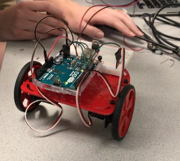
Now we had a functional free-roaming robot, almost. Our battery pack was too bulky to fit on the robot so I held it overhead.
Here is our final product:
Our code to make it spin in alternating circles is shown below:
//robot's first journey

#include <Servo.h>
//create servo objects, I/O pins
Servo servo_right;
Servo servo_left;
char servo_right_dig_pin = 10; //we use char because it takes less memory than int or float
char servo_left_dig_pin = 11;

void setup() {
  servo_right.attach(servo_right_dig_pin);
  servo_left.attach(servo_left_dig_pin);
}

void loop() {
//spin one way, wait 5 seconds, spin the other way
  turn_left_wheel();
  delay(5000);
  turn_right_wheel();
  delay(5000);
}

void turn_left_wheel() {
//hold right wheel still and spin left one
  servo_left.write(110);
  servo_right.write(90);
}

void turn_right_wheel() {
//hold left wheel still and spin right one
  servo_right.write(70);
  servo_left.write(90);
}
Click the image to watch our robot drawing a circle!
That’s the end of Lab 1. Thanks for coming!