Intro to the Arduino, Servos & US Sensors
Description
In this lab, we completed the assembly of our robot with servo motors and ultrasonic sensors. We learned the basics of programming Arduino Nano, and used built-in functions to control digital and analog pins to let the robot perform autonomous driving.
Part 1: Assembly of Robot
The kinematics of the robot is a differential drive, which is the movement based on two driven wheels. We attached two servo motors that control forward/back and turning movement on either side of the robot frame and a caster wheel that supports the robot body in the front. Then, we used Velcro to fasten AA Battery Holder & 9V battery to robot frame. The AA battery will be used to power servos, whereas the 9V battery is an alternative way to power Aduino. The breadboard, placed on the top of power supplies, is where we attach Arduino board and build circuit.
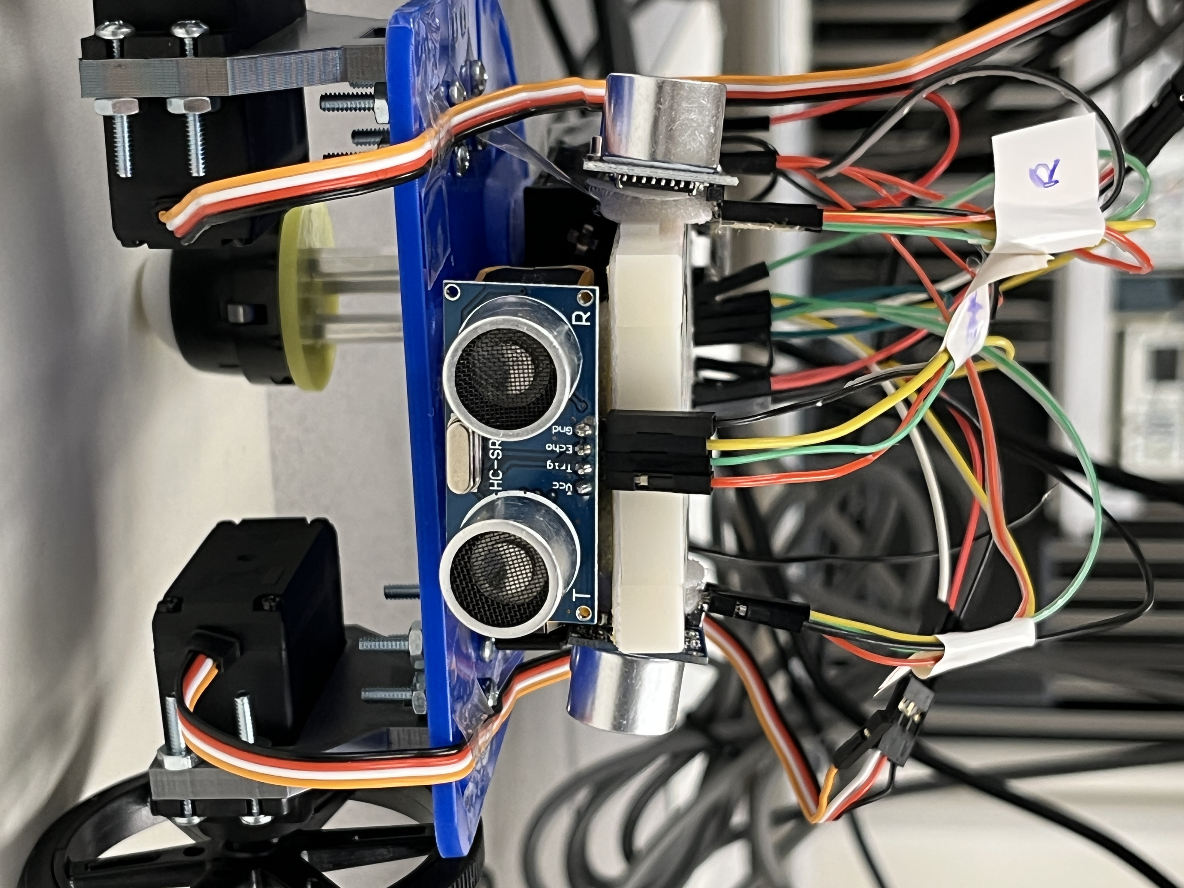
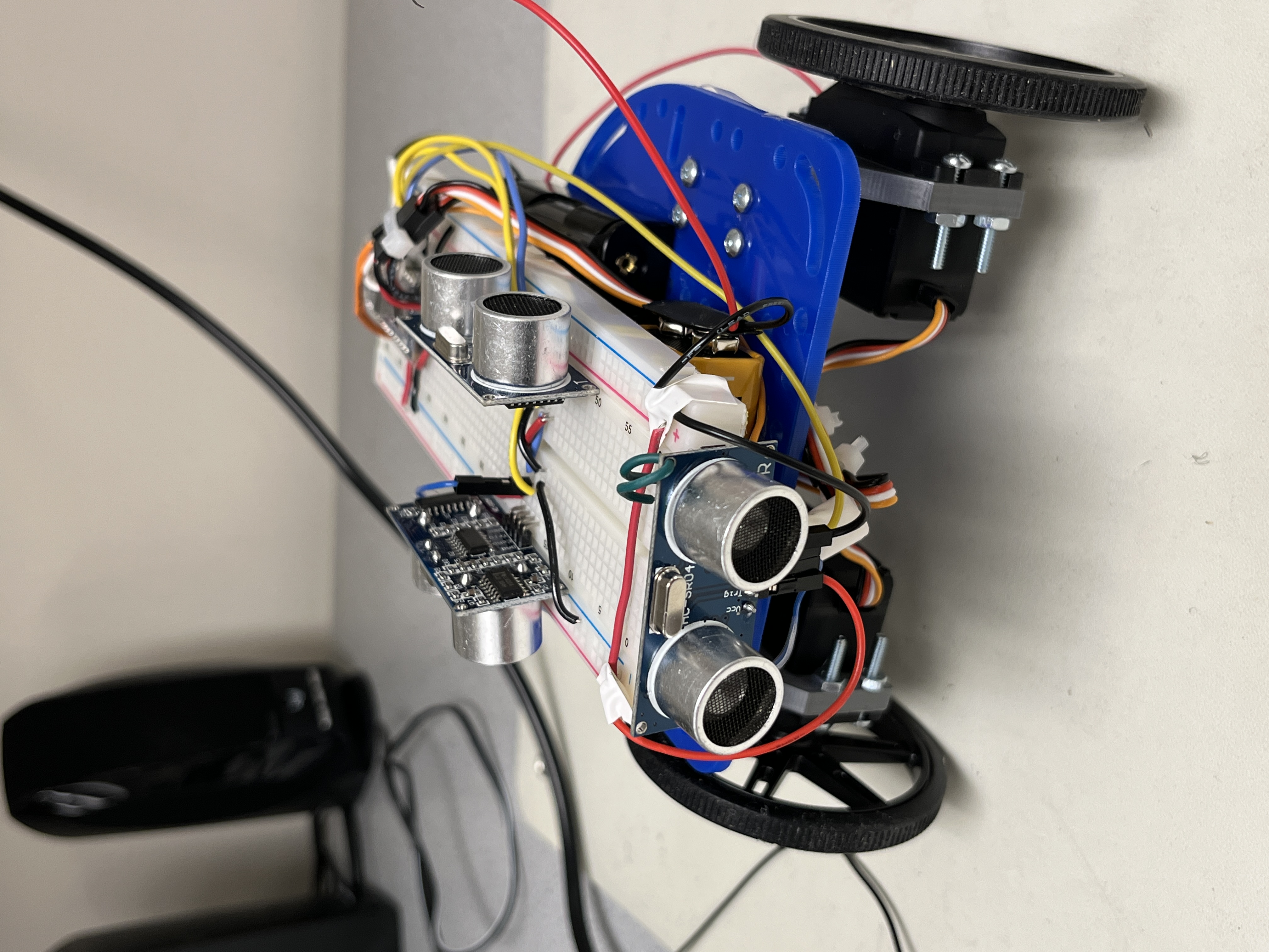
Fig.1. shows our robot after construction. However, the breadboard wiring like this is not neat enough, which might be really hard to debug when we add more electrical components later on. Therefore, after we finish Lab 1, we spend some additional time rearranging US sensors’ positions and redesigning wire harnesses. Fig.2. shows a much neater robot after our refinement.
Part 2: Blinking LED
We started with a blink_LED.ino example code to get familiar with Arduino IDE. In the example code, we learned that the Arduino’s onboard LED is connected to D13 pin. We can turn on or turn off the LED by setting D13 pin to high or low. As for the blinking frequency, it can be adjusted by delay() statements.
Part 3: Servos
We completed Servo Demo, which requires us to program our robot to make it move straight forward, turning left and right, and turning 270 degrees. Based on this demo, we wrote helper functions moveForward(), turnLeft(), turnRight(), etc.
During our second lab session, we replaced 4.5V AA battery pack with 6V. One nice thing is that we observed our servo motors running at a much higher speed, but, sadly, helper functions such as turnLeft() we wrote previously need to be retested and modified since the delay time will be different.
While spending hours and hours testing time duration for robot turning, we thought if we could implement turning functions using servo’s feedback. We found out that the feedback range for the servo is not exactly 0-1023. By running a loop that spins wheels slowly and display analogRead() on the serial monitor, we determined the actual feedback range for two servos.
There are still some servo problems that we need to solve in the future:
- Because of inertia, different motor speeds would result in slightly different angles that the robot turned while the turning degrees we programmed are the same.
- Our right servo became much slower than the left one.
Part 4: Ultrosonic Sensors
To measure distance and navigate in the maze, we positioned one US at the front of the robot, one on its left, and one on its right. We tested it using the example code told in class and made sure that three US could accurately measure distances.
With the help of US sensors, we developed a function detectObj() that automatically stops the robot when the front sensor detects an object within a fixed distance.
Part 5: Autonomous Driving
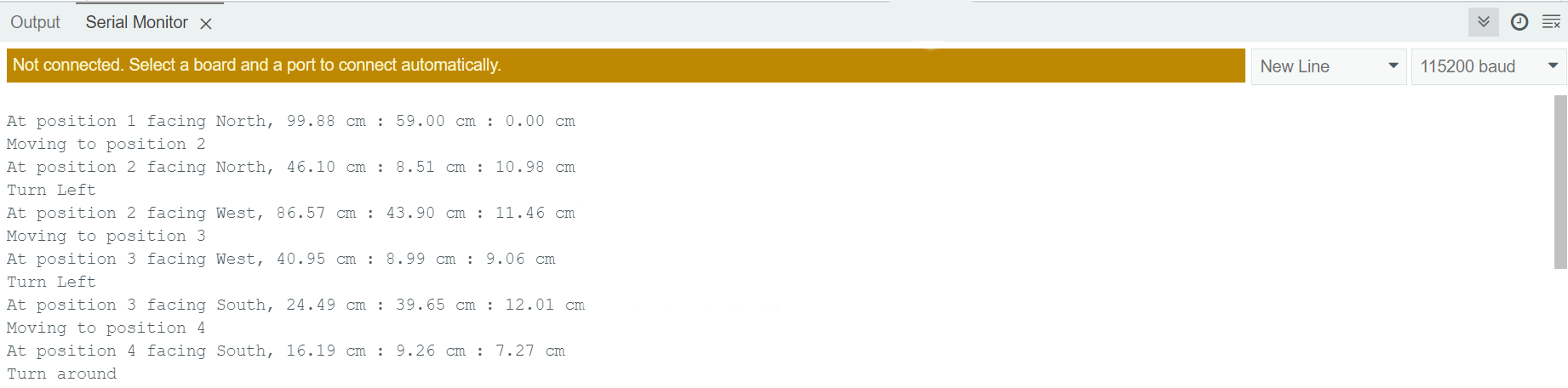
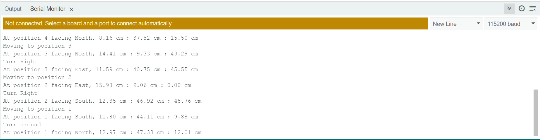
Finally, we integrated our robot movement functions and detectObj(). Our robot learned how to drive around a simple maze! As shown in Fig.3., the Serial Monitor describes what the robot does and prints out US measured values at certain positions.
To make sure the robot stays in the middle of two walls while moving forward, we wrote the function adjustDir() that automatically adjust direction based on distance measured by the left and right US sensors. See how it works!
Part 6: Photo of Us!