Filtering and FFT
Description
In this lab, we built the audio aspect of our robot so that it will be able to detect a specific trigger frequency that act as a signal to start robot navigating. In case there the microphone circuit does work as expected during final demo, we also installed an override start button.
Part 1: LTSpice
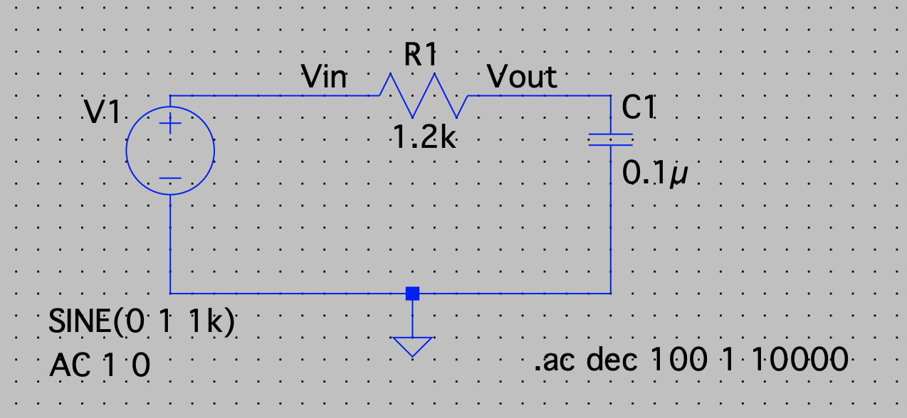
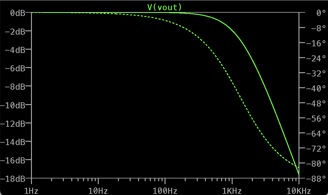
The behavior of filters are simulated using LTSpice. We first draw a low pass RC circuit with R=1.2Ω and C=0.1μF using LTSpice, as shown in Fig.1. Then, we simulate the frequency response of the cirucit from 1Hz to 10kHz by using an AC voltage source. On fig.2, we can observe that the circuit passes low frequency signals, and as frquency gets higher, Vout decreases.
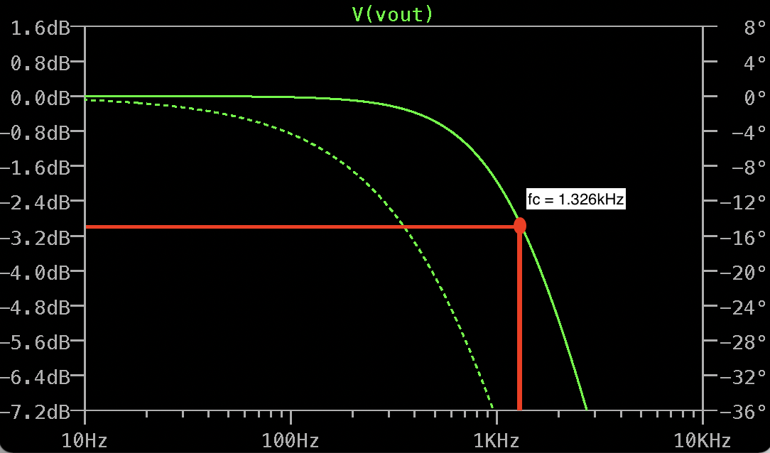
The cutoff frequency is approximated by marking the point that is at -3dB, as shown in fig.3. By doing that, we get a cutoff frequency of about 1.325 Hz. Compared with the cutoff frequency calculated using formula 1/(2πRC), we confirmed the approximation gived us correct result - both are around 1.3 Hz.
We also simulate a high pass filter withe the same values for R and C as for low pass filter. The frequency response of the high pass filter shows opposite behavior compared with low pass filter. Just like what did before, we approximated cutoff frequency and compared it with calculated value - both are around 1.3 Hz.
Part 2: Build the Microphone Circuits
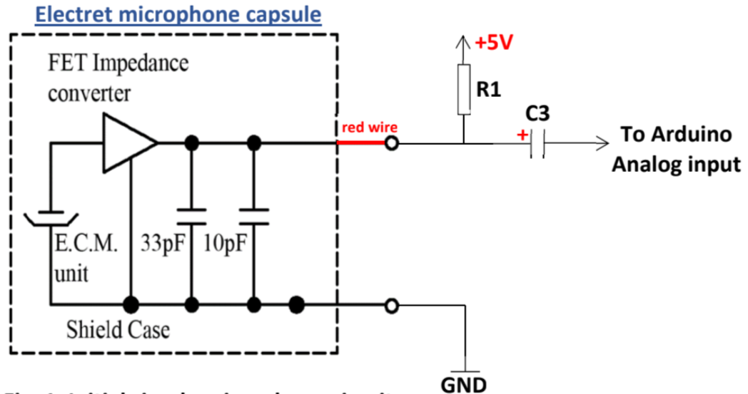
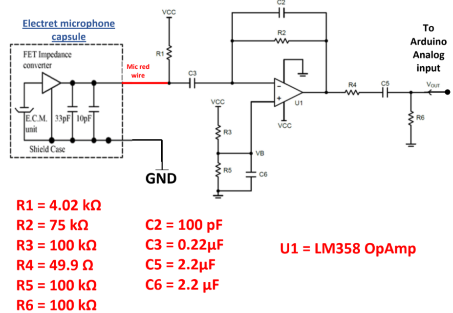
We moved on to the audio aspects of the robot. A microphone circuit is built to collect sounds that will be processed by Arduino. We started with building the microphone circuit without amplification shown in Fig. 6, using R1=4.02kΩ and C3=0.22μF.C3 froms a highpass filter with R1, which can attenuate low frequency signals that are not useful.
Part 3: Code the Arduino and MATLAB to Characterize Circuits
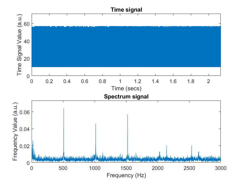
To test the micropohone circuit, we coded our Arduino to collect sound and used MATLAB to perform fourier analyze. Instead of using analog_read(), we code ADC on the Nano and set it to Free Running Mode so that we can read its value by calling ADC0_read(). In MATLAB, we code it to generate sound with initial frequency of 500Hz, final frequency of 500.1 frequency, and sound duration of 2s. The MATLAB will also perfrom fourier analyze on data collected from arduino and generate a signal spectrum in the end. The sound was generated from our computer speakers when we run the MATLAB code, and the microphone was positioned close to computer speakers to collect data. After data collecting, MATLAB perfromed fourier analyze and produced graph shown in Fig.7. From graph, we can observe peaks at frequency 500Hz, 100Hz, and 1500Hz, but there are noises at other frequency values and spetrum’s values are relative weak at desired frequencies.
Part 4: Imporve the Microphone Circuit: Amplifier Circuit
We the further improved the design microphone circuit shown in Fig.7.
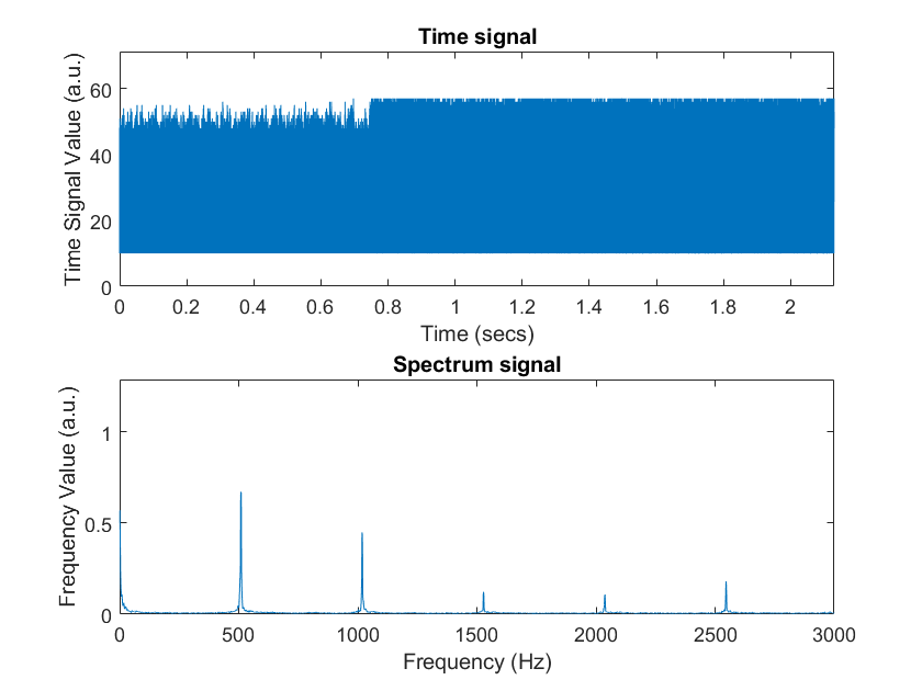
We tested the amplified circuit with the same procesure we did to test unamplified circuit. The MATLAB produced a graph shown in Fig.8. We observed that peaks at frequency 500Hz, 1000Hz, and 1500Hz are much higher than before, and at the same time, noises “dispeared” on the graph.
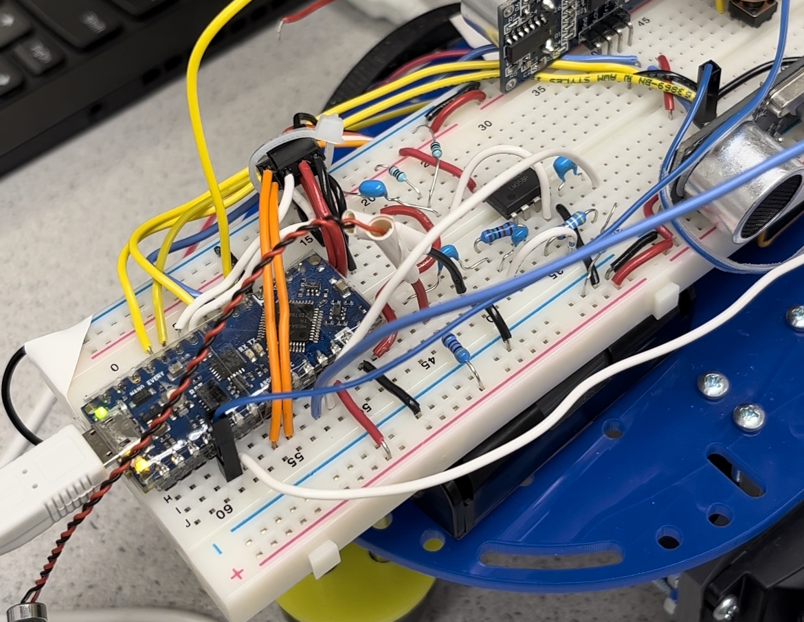
Check out how the circuit is built on the robot in Fig.9.
Part 5: FFT on Arduino
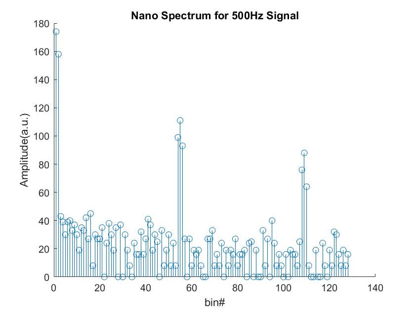
In the final demon, MATLAB will not be used to perform Fourier analysis, so we need to perform it on the Arduino. To do this, we need a libary called “FFT” to program the onboard Fourier transform. We modified our code to accumlate ADC sampled values (257 values will be aquired) using interrups on TCA. The TCA is set to normal mode, overflow interrupt, disabling event counting, and an interrupt inverval of 0.41667ms (using clock division of 64). After 257 values are captured, TCA is disabled and FFT library is used to process Fourier transform. Once the output of fft is printed on Serial Monitor, we copied all the values to MATLAB and ploted theme using function stem.
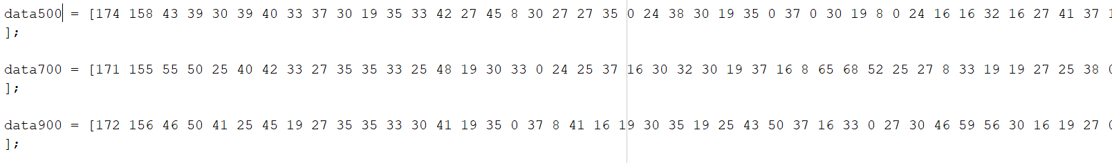
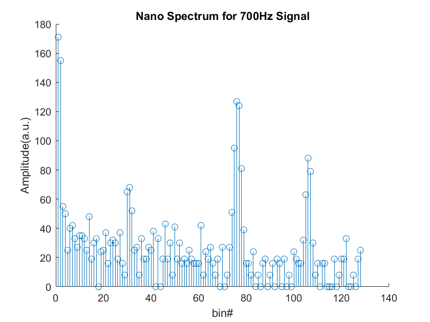
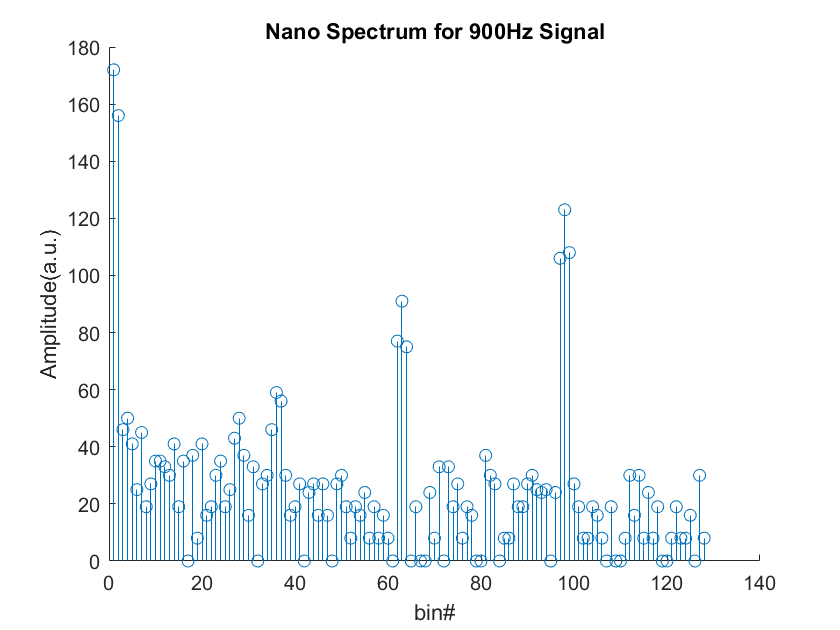
Fig.11 is the spectrum we contained with a sound frequency of 500Hz. We then repeated testing our code using sound frequency of 700Hz and 900 Hz, shown in Fig.12 and Fig.13.
Part 6: Override Button
The robot needs an override button to signify robot start navigating if the robot fails to identify the specific frequency of the sound. We decided to use internal pull-up resistors for the override button circuit since it will save us some space on the breadboard. We now have LED turns one when the button is pressed just to make sure the override button works. In the furture, we will program our robot so that when the button is pressed, robot will start navigation.