RF Communication, Navigation, and Finalizing Robot
Description
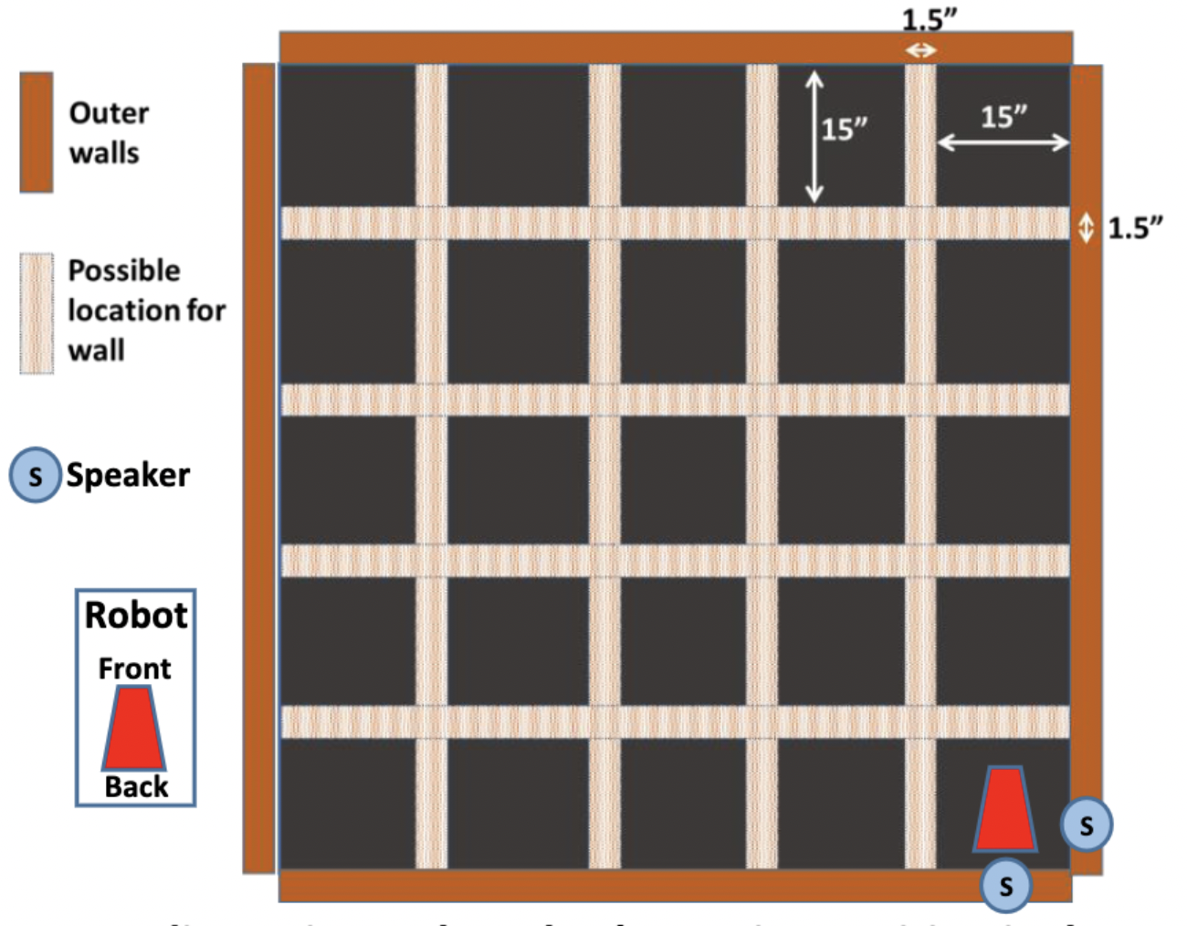
In the final lab, we worked on implementing RF communication, DFS navigation, PID control, and combining all codes we did so far. Our goal is to program the robot so it navigates the maze and completes various during the final demo. Fig.1 shows the overall dimensions of the maze. In the beginning of the demo, the robot will be positioned to the lower-right corner of the maze. It will remain at the starting position of the maze until it detects a 440 Hz frequency. In case the robot fails to identify the frequency, an override button should be implemented to indicates the beginning of navigation. The robot will search the maze using DFS algorithm and continously look for treausures, which are IR LEDs at different frequencies. Every time when a treasure is found, robot will measure the treasure’s frequency and send the frequency to base station, where the frequency value will be desplayed. After total of two treasures are found, robot will imediately stop navigation and then blink its onboard LED.
Part 1: RF Transcievers
With RF transceivers connected into both base station’s and robot’s breadboard, we tested the communication with example code provided. To build the communication between two, the pipe numbers for base station and robot should be matched. We calculated the pipe numbers by following: pipe numbers = 𝟐∙(3∙D+N)+X (where D is the day of the week on which your scheduled lab takes place; N is our team number; X is 0 for the transmitter and 1 for the receiver). In this way, we came up with unique pipe numbers and avoided signal interruptions from other teams. After the communication worked, we adopted code provided and developed an function for robot that continously sends measured frequency to the base station until the transmission is successful or time outs.
Part 2: Non-Blocking Coding
We went through all code that we programmed and replaced blocking statement delay() with non-blocking statements like delayMicroseconds() and milis(). You can see from the final demo video that the motion of robot is very smooth and no obvious pauses happened when navigating the maze.
Part 3: FFT & Override Button
By using the same method of performing FFT and obtaining spectrum in lab 3, we tested and compared the spectrum when the robot react to 300, 400, 440, 470, 500, and 500 Hz frequencies. We observed that at frequency 440, a peak would occur between bins 45 to 50. Every time when 257 sampled values are collected, the nano will perform FFT and check the output value around bin 47. If there is no peak at desired bins, ADC will be reset and TCA overflow interrupt mode will be re-enabled. The process will repeat until the robot detects the 440 Hz frequency. After modifying the FFT code from lab 3, we tested using example audio that includes a series of notes at different frequencies. We ensured that navigation start would start only when the 440 Hz note appeared.
The robot needs an override button to signify robot start navigating if the robot fails to identify the specific frequency of the sound. We integrated override button code with FFT, so when navigation would start either when is440 flat is triggered or override button is pushed.
Part 4: Navigation
We implemented DFS so that the robot can navigate intelligently and covers every single block of the maze. I used a third party stack library so that it’s easier to push and pop a value from it. Also, this library make it simplier to search through the list and delete an element from any location and push that element to the front. Although DFS works theoretically, when we tested it on the robot, we found out that there are so many noises that could interrupt normal flow of the DFS. For instance, we have a function called moveForwardOneBlock() that moves the robot in a fixed distance to the middle of the block in front of the robot. However, when we apply PID to correct robot’s path, the moveForwardOneBlock() may not move the robot to the location we expected due to the wave correction.
The video below shows how noises could amplify errors of navigation. The robot at begining is going very straight in the middle of walls, but suddently PID control makes the robot a little off angle. When there is not wall on the right that could be used as PID input, the robot performs moveForwardOneBlock() and moves further way from its ideal path. The error accumulates and robot losts its way very soon and eventually his the wall.
To solve this problem, we first raised minimum servo speed that can be ajusted by PID control. This could reduce changes in angle due to PID control and lead to a much smooth motion. Also, I improved moveForwardOneBlock() so that it uses US sensor measurements to correct robot’s location. For example, the function will also make sure the robot to it’s front wall is at a fixed distance everytime when it is at edge blocks or deadend. Another thing we did is to reduce servo’s speed. When we tested robot turning at a high speed, the turing angles are slightly different everytime (can see by eyes). Whereas, at a lower speed robot’s turning are more stable and accurate.
Part 5: PID Control
PID control might be the part that took us the longest time to test and ajust. We used right US sensor as input and a setpoint value of 15. When right US sensor measures a distance of 15, PID will generate an output of 0, which indicates that robot is in the middle of the walls and therefore no two servos should rotate at normal speeds. When the error (=setpoint-input) is positive, the robot is to close to the right wall, so the left servo needs to slow down with a ratio depending on PID output. This will make the robot move leff and get further away from the right way. when the error is negative, the right servo will slow down and robot will move closer to the right wall.
We thought about automatically switching input sensors: when the robot is at the middle of two wall, it will use the difference of left and right US sensor data as input with a setpoint of 0; when only one side has wall, only one sensor will be used as input with a setpoint of 15. We coded the robot to do that, some obvious wave motion are caused by switching PID input. Since we don’t have enought time to test and improve this plan, we decided to use our origional PID, which is only using right US sensor and disabling PID when no wall on the right.
With coefficients k-p, k-i, k-d that we tested over hundreds of time, we are so impressed that our PID eventually performed really well and provided a nice position adjustment for the robot.
Part 6: Freqeuncy Measurement & Display
The robot should regulary look for treasure when it navigates around the maze. We used the new code provided on canvas and modified it so it can cycle through three phototransistors and detects frequency in three different directions. Then, I coded the frequency measurement procedure: when a frequency is detected, the robot will immediately stop if no treasure has been found (foundTreasure = 0) or if the frequency detected is not close to the first frequency measured (making sure is a different treasure). Otherwise, the robot will continue exploring. When robot meets the stop condition, it will stay at its current position and collects 20 frequency samples. If the robot couldn’t collect 20 samples before time out, it will resume its navigation. If it successfully collects 20 samples, the arrary that stores all the samples will go through sorting and mod to find the most frequent element. The output frequency will be sent to base station and displayed.
Final Demo
Nights and nights of testing and modifying eventually paied off! Our robot navigated the maze with very mimimum collisions to walls and found both two treasures with correct frequency measured during final demo. Although during first time demonstration the base station was not displaying any frequency, we figured out the issue was due to a broken transceiver. The transceiver worked properly the night before demo day, but accident still happened! After we changed a new tranciever, the base station worked and displayed correct frequency. Check the video below how our robot navigates the maze!
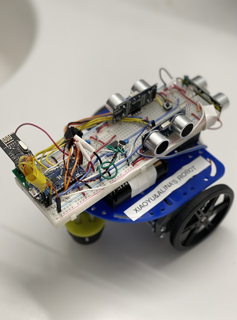
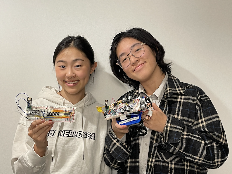
Gallery