training-labs
Lab 1: Arduino Setup, Hardware Inventory, and Thermistor Principles
The goal of this lab is to set up the Arduino environment for this course, check that you have all needed items in your training kit, understand the principles of two temperature sensors, and collect temperature data. Being able to collect data from sensors is a foundational skill used in later parts of this course.
Environment Setup (Prelab 1)
Please follow the instructions for setup.
Please ensure that you have installed the following:
- Arduino Desktop IDE
- MCCI Board Support Pack
- MCCI Catena Arduino Platform Libraries
- Adafruit MCP9808 Library (and dependencies) from the Arduino IDE Library Manager (Tools->Manage Libraries)
Lab Excercise 1
By completing this lab, you will be able to:
- measure temperature using a thermistor and digital temperature probe
- compare readings from both temperature reading devices
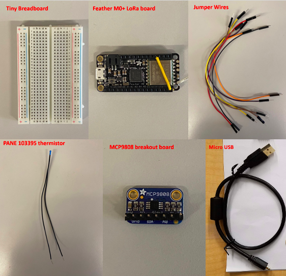
Materials
- Tiny breadboard
- Feather M0+ LoRa board
- Jumper wires
- PANE 103395 thermistor
- MCP9808 breakout board
- MicroUSB cable
- 10k ohm resistor
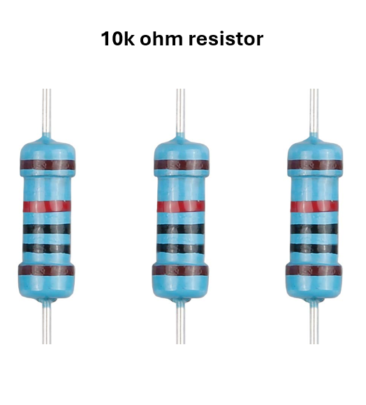
Please check that your Training Kit has all of these materials. Note: make sure you pick the correct resistor in your student kit to use by following the correct color bands as shown in the image. If you are not sure, ask a TA or use a multimeter to measure the resistance of the resistor.
Analog Circuit
Thermistor
A thermistor is a type of semiconductor made of materials with known resistances that change their resistance non linearly in response to the temperature based on the composition of the thermistor. These can either come in an NTC (negative temperature coefficient) or PTC (positive temperature coefficient). The Pane 103395 (datasheet) is a type of thermistor that Loses Resistance as the Temperature Increases.
As a result, we can connect it into a voltage divider where the other resistor is known and measure the resistance in comparison to the other resistor.
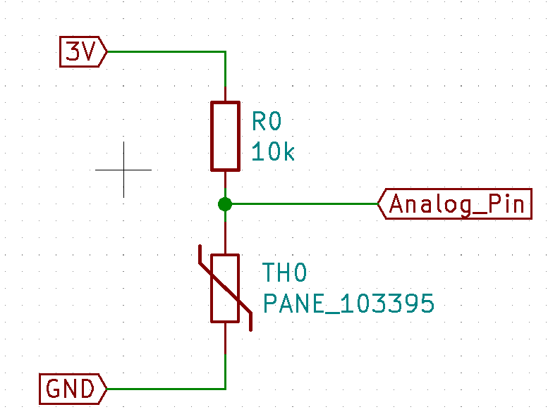
Circuit Setup
To make the analog circuit, first, ensure that you have not connected the Feather to anything through USB.
Run a jumper from the Feather’s 3V pin to one leg of the resistor. The other leg of the resistor should be connected to one leg of the thermistor. The other leg of the thermistor should be connected to the Feather’s GND terminal (use another jumper wire). Connect the node (another word for a place where two or more component terminals meet) between the resistor and thermistor to an analog pin of the Feather board. We will assume that you connected it to A0, but any of the analog pins will work for this task. Now, temporarily disconnect that connection to A0.
Aside: Series Resistor for prototyping safely
You can place a moderate-value (i.e. 1k Ω) resistor in series with signal pins (analog or digital) to reduce the consequences that something blows up while prototyping circuits. Why does this work? Ohm’s law states that a maximum 3mA of current will flow through that resistor.
Arduino Sketch Settings
We will use the MCCI Catena 4410 board (whose BSP you installed when you completed the environment setup at the beginning of this lab). Please select that board in Board submenu of the Tools menu.
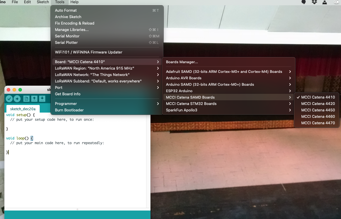
Plug in the Feather board
by USB and select its serial port in the Port submenu of the Tools menu.
You now have a blank sketch (with just setup() and loop()
functions that you will fill in).
Printing over USB Serial
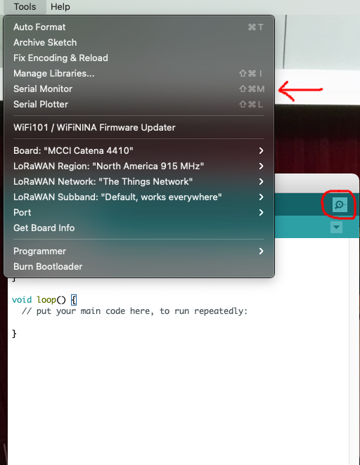
An easy way to get feedback from the Feather is by printing over the USB serial interface. Printed text appears in the Serial Monitor, located in the Tools menu or by pressing the dotted magnifying glass in the upper right corner of the Arduino IDE window.
You can print different kinds of variables over the USB serial interface.
You must issue a call such as Serial.begin(115200); to initialize that
interface. Place such a call into your setup() function.
In that case, 115200 is the baud rate and must match the baud rate shown
in the Arduino Serial Monitor. You can print single datatypes (i.e. just a
string, just a float, just an int, etc.) using the print and
println functions. Example: Serial.println("Hello");
PANE 103395 thermistor
Temperature Theory and Calculation
We know that in our voltage divider,


We solve for Rth.

Since we have a formula for the thermistor’s resistance, we have to find which temperature corresponds with that resistance. As we stated above, a thermistor changes its resistance with temperature nonlinearly. The exact relationship can be complex, so we will use an approximation. The datasheet gives experimentally-derived coefficients for an approximation known as the Steinhart-Hart equation. However, the coefficients are in terms of the ratio the thermistor’s measured resistance to its nominal resistance. The coefficients also depend on which range that ratio falls in. So, to use the datasheet’s equation, we take that ratio (Rth/10000, since the datasheet declares the nominal resistance to be 10 kΩ ), determine which range the ratio falls in, and use the corresponding coefficients to arrive at a temperature.
Now, you will implement this temperature finding process in a C++ program.
To make our code more easily testable, we will implement a helper function to get the unknown resistance (the thermistor) using the supply voltage, voltage divider voltage, and the known resistor value.
/*
  Get the "unknown" resistor using voltages and the known resistance.
  This function assumes **voltages**, not raw values from analogRead.
  On Feather M0+ LoRa with default settings, pass vdiv = (3.3/1024)*analogRead(pin).
*/
static inline double getUnknownResistor(double v, double vdiv, double known_r){
  return known_r * vdiv / (v - vdiv);
}
Put the getUnknownResistor function above any other functions that use
it, such as your setup() or loop() function. We will use another
helper function to use the Steinhart-Hart equation given on the thermistor’s
datasheet.
/**
  This function uses information from the PANE 103395 datasheet, rev 0.
  Returns NAN if the resistance ratio is outside of the specified resistance
  ratios on the datasheet.
  Numeric values come from the datasheet.
  r_r25 is the ratio of the thermistor resistance to the thermistor resistance
  at 25 degrees C. In other words, it is r/10,000 since the thermistor is a
  10k thermistor.
*/
static double tempFromResistance(double r_r25){
  double a, b, c, d;
  if (r_r25 > 66.97){
    return NAN; //"Not a Number" ~= undefined. We're outside of the datasheet range!
  }
  else if (r_r25 > 3.279){
    // Coefficients taken from datasheet
    a = 3.357296E-03;
    b = 2.508334E-04;
    c = 4.189372E-06;
    d = -6.240867E-08;
  }
  else if (r_r25 > 0.3507){
    a = 3.354016E-03;
    b = 2.541522E-04;
    c = 3.730922E-06;
    d = -7.881561E-08;
  }
  else if (r_r25 > 0.0637){
    a = 3.361395E-03;
    b = 2.582266E-04;
    c = 5.885012E-07;
    d = -2.823586E-08;
  }
  else if (r_r25 > 0.0169){
    a = 3.351295E-03;
    b = 2.500181E-04;
    c = -1.7255607E-07;
    d = -4.356943E-08;
  }
  else{
    return NAN;
  }

  // Steinhart-Hart equation taken from datasheet (don't need to learn)
  return 1/(a + b*log(r_r25) + c*b*pow(log(r_r25),2) + d*pow(log(r_r25),3));
}
The datasheet for our device gave coefficients for the Steinhart-Hart equation to get a better approximation of temperature. Other datasheets might give other equations and coefficients to use similarly.
Aside: Performance
log()and floating point exponentiation can potentially use up a lot of CPU resources. If we wanted higher speed instead of higher accuracy, we could use a linear or piecewise linear approximation instead. If your code is too slow, consider trading some accuracy or precision for speed.
Reading an Analog Value
Reading analog values can be challenging because the analog-to-digital
converters (ADCs) on microcontrollers can have many parameters that require
careful reading to understand. However, the developers of Arduino cores
have chosen default parameters that generally work for low-performance
cases. Use analogRead(pin) to get an analog value using those default
parameters. analogRead(pin) returns
a 32-bit unsigned integer of which bits [9:0] are significant, and the rest
are 0. Here, “pin” refers to the name of a analog pin on your board.
The ADC has linear weighting and references 3.3V, so the result N represents a voltage:

Before declaration of any function, define a const int for the specific analog pin that you want to read from (in this example, A0) with #const int PIN = A0;. Define a static uint32_t a_val; in your loop() function. It is
often useful to define static variables in this way so that they retain
their value between function executions but do not clutter a large namespace.
Update a_val = analogRead(PIN); You can then print a_val to Serial
with Serial.print(a_val);.
We can finally implement a getTemperature function.
const int PIN = A0;
//rest of your code

double getTemperature(){
  //10000 below is from the 10k fixed resistor
  double thermRes = getUnknownResistor(3.3, (3.3/1024)*analogRead(PIN), 10000);
  //10000 below is the nominal thermistor resistance at 25 degrees C
  return tempFromResistance(thermRes/10000);
}
Serial Plotter
If a_val is the only thing that you are printing in your loop()
function, the Serial Plotter (found in the Tools menu) can plot its value
over time. Check out this
Adafruit Link
to learn more about the Serial Plotter.
Upload the Sketch
Try starting Serial and print()ing some values.
Use the arrow button on the Arduino IDE to compile and upload your sketch.
Test your thermistor code
Try warming up the thermistor to see if the measured temperature increases.
I2C Temperature Sensor
Sometimes, it is desirable to use a digital sensor. The MCP9808 is a digital temperature sensor that uses a two-wire interface. Inter-integrated circuit (I2C, “I squared C”) and SMBus are branded examples.
I2C allows multiple sensors to cooperate using just two wires. Each sensor only sends data when addressed by the microcontroller. Sensors ignore any requests not addressed to them.
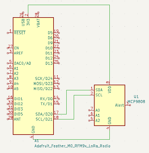
To physically connect an I2C peripheral device, connect the corresponding 3V/VDD, GND, SCL, and SDA terminals on the microcontroller and I2C peripheral.
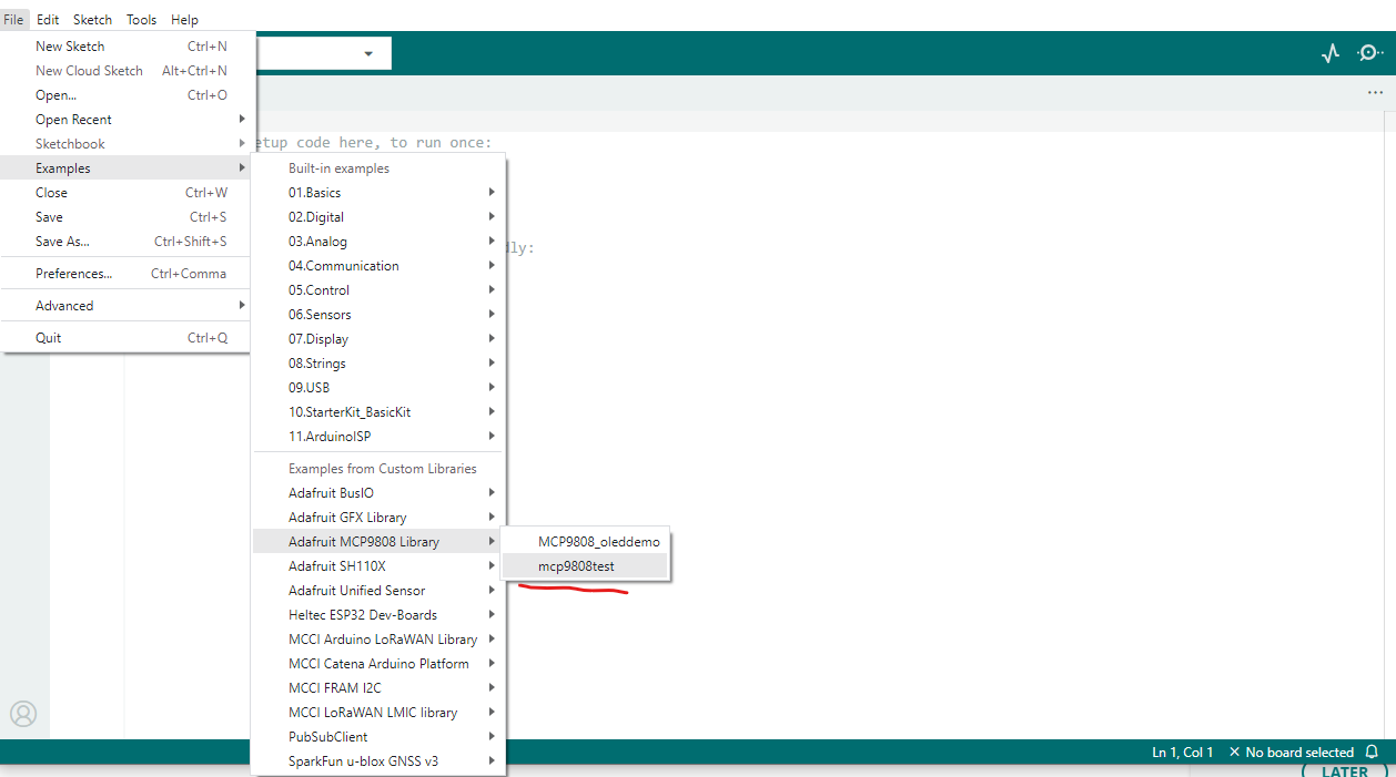
The MCP9808 has a premade library that we will use. The Adafruit MCP9808 example
mcp9808test gives an example of how to set up and read from that sensor.
You can find examples by going to File->Examples->Adafruit MCP9808->mcp9808test. Also see picture below for instruction.
All of the functions you need appear in that example. Here is some skeleton code to get you started.
//Place this in your sketch
#include <Adafruit_MCP9808.h>
//...Other stuff


double getTemperatureDigital(){
  //you will implement this
}
Hints on how to use Adafruit_MCP9808 based on library code example:
- You need to initialize the MCP9808 before you can use it. The
setup()function is a good place to callbegin()functions for sensors. - Can you make your themistor and digital sensor examples return similar values? i.e. all give values in degrees C, degrees F, or K
Comparison of Temperature Sensors
Please print temperature data from both analog and digital temperature sensors
on the serial monitor every 10 second. You may use delay(t) in your
loop() function to slow down printing, where t is the pause time in milliseconds. For example, delay(1000) means pausing for 1 second.
Please explore how the analog and digital temperature sensors compare to each other. Do they agree? If they measure higher or lower temperatures, does the agreement change?
Deliverables
Questions
Please answer the following questions. Please cite any references, but acceptable answers should all be on this course website.
- Where on the datasheet are the a,b,c, and d values for the thermistor?
Comparison
- Please write a small paragraph about comparing the data you collected from the digital temperature sensor and the analog temperature sensor. What may be the reason causing this difference.
Summary of results
Please include a file with some temperature data that you collected from both sensors. A text file of copy-pasted Serial Monitor output is fine.
Code
Please include your Arduino sketch files (your .ino file for this lab), and if you used any code that is not yours, please make a comment on that line and cite the source.
Canvas Submission
Please submit everything (1. Word file or pdf of your answers, 2. Summary of results, 3. Your .ino file) as a .zip file on Canvas.