Lab 1 Artemis
Introduction
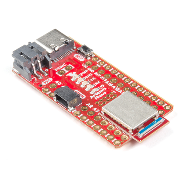
The objective of the first ECE 4960 lab was focussed on setting up the Arduino IDE and the SparkFun Redboard Artemis Nano. The Built-in Examples provided by Arduino and the Examples for RedBoard Artemis Nano provided by the Apollo package were used to program the board and test its functionality. This lab helped me explore the functionality and familiarize myself with the board as well as the Artemis module.
Set Up
First, I downloaded and installed the latest version of the Arduino IDE (1.8.19). Then I connected the board to my computer using the USB-C cable provided. Using the instructions in Artemis Development with Arduino guide, I set up the SparkFun Apollo 3 Arduino Core to manage the Artemis board. I used the Blink example described below to verify that the core was installed correctly.
Initially, I had used the Arduino IDE 2.0.0 Release Candidate builds, but it did not have Apollo 3 board package.
Artemis Board Functionality
Once the Arduino IDE had been set up, I ran the examples listed below. With the Artemis board was plugged in, I selected the “RedBoard Artemis Nano” board under the “Tools > Board > SparkFun Apollo 3” and chose my USB port. All the examples used are Arduino sketches with .ino file extension and followed the structure of Arduino programs. Consisting of a setup() function, which is run once when the board is powered or reset and a loop() function, which loops over consecutively.
Blink It Up
The basic Blink example turns onboard LED on for 1s and off for 1s repeatedly. This particular example is a generic one usually used to verify that code can be uploaded to boards. I loaded the exampled from File > Examples > Built-in Examples > 0.1 Basics > Blink and clicked the Upload button, which compiles and uploads the code to the board.
Serial
The Apollo3 contains two UART peripherals, which can be included be used with Arduino Serial API. The Serial Example (File > Examples > Artemis Examples Example04_Serial) was used to communicate with the board over serial. I tested that the example by providing input to the serial port using the serial monitor and ensuring that it was echoed/returned in the serial monitor. I had to change the Baud Rate in the serial monitor to 115200 to match the code.
Analog Read
The Analog Read example (Files > Examples > Artemis > Example02_AnalogRead) demonstrates using the analogRead function to get the readings of the temperature sensor via the on-board ADC. Touching the chip to increase the temperature, is reflected correctly in the serial monitor readings with an increase from 35000 to 39000 in raw temperature readings.
Microphone Output
The Microphone Output example (Files > Examples > Artemis > Example1_MicrophoneOutput) is used to test the pulse density microphone on the board. I tested this example by playing sounds at increasing frequencies and ensure that it was reflected highest frequency displayed on the serial monitor.
Conclusion
This lab was a great introduction to the Artemis Board and helped me familiarize with its different components and features. I tried to modify the example codes and run other examples to get a better understanding of the board. I am excited to the work with it in the future!