Lab 5
Open Loop Control
The goal of this lab was to achieve an autonomous battery powered robot which can execute a pre-programmed sequence of moves. We replaced original circuitry of the car with the Artemis board, two dual motor drivers and sensor circuitry to get open loop control of the car.
Motor Drivers
The RC car has two motors each controlling the wheels on one side (left /right) of the car. A dual motor driver has two channels which can be used to drive two DC motors. To ensure that our is fast, we used one dual motor driver to drive each motor by parallel coupling the two inputs and outputs, so both the channels are used to drive the same motor. We can deliver twice as much current without overheating the motor driver chip. We chose to parallel couple channels on the same breakout board instead of motor drivers on different boards because both the channels operate with the same clock circuitry so there will be no timing difference.
We need to connect the Artemis board to the motor driver inputs to control the speed of the motors. Each motor driver channel needs two inputs which can deliver PWM signals. I wanted to place my Artemis board vertically in the chassis, so I choose pins on the same side of the Board.

I connected and tested the motor drivers one at a time. To bench test the motor drivers, I shorted the following pins – (A1IN, B1IN), (A2IN, B2IN), (A1OUT, B1OUT), (A2OUT, B2OUT). I connected the input channels and GND pins to the Artemis pins. I powered the motor driver using an external DC power supply with 3.7 V and a moderate current limit. I chose this setting as fully charged 850mAh battery has a terminal voltage of 3.7V (lab 4).
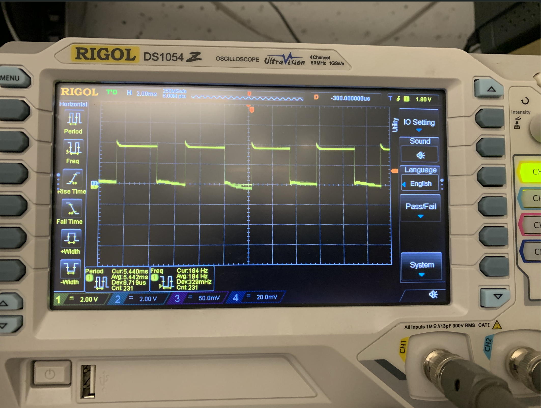
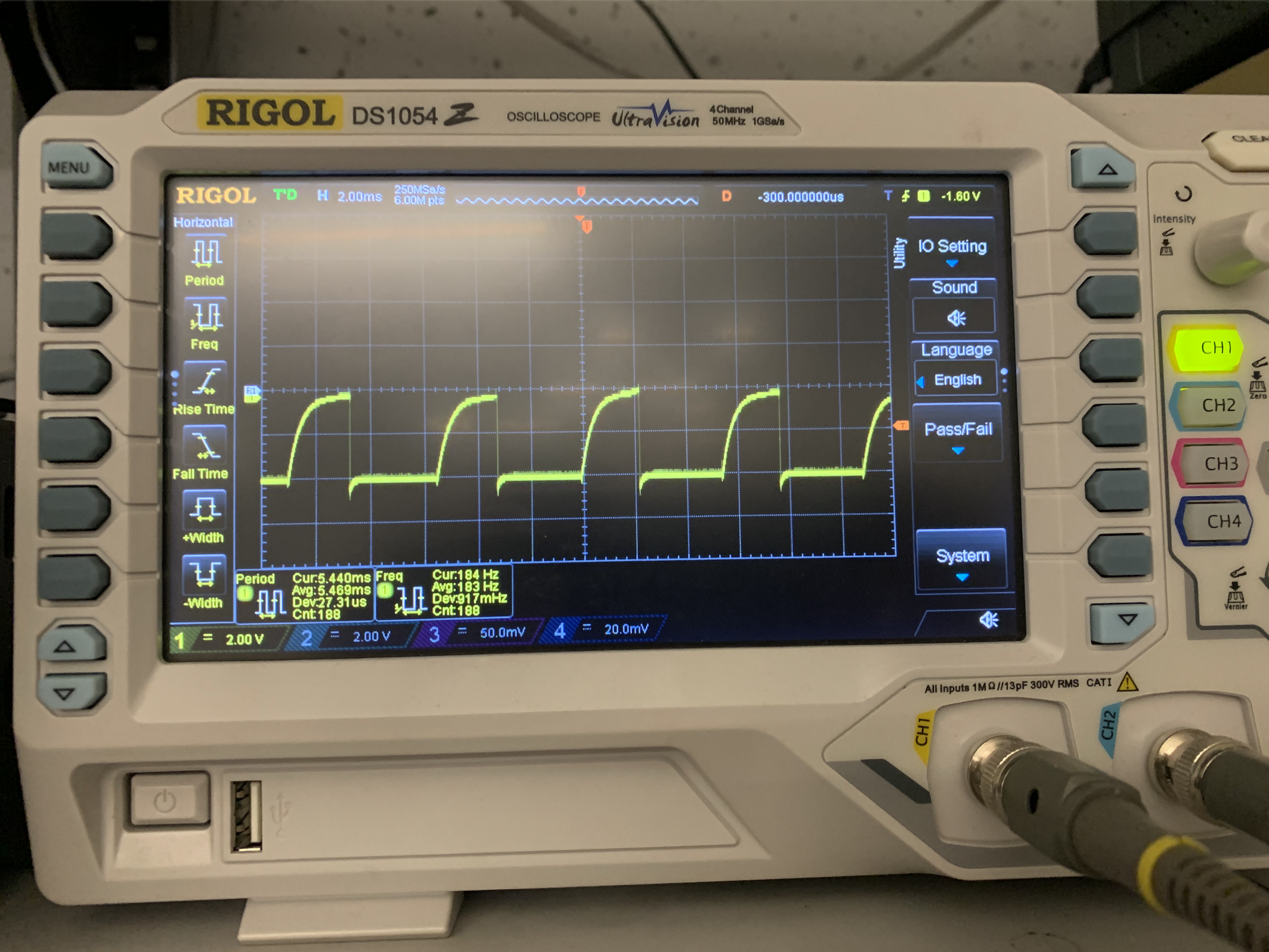
To generate the PWM signal, I used analogWrite() function which writes a PWM wave to the pin as shown in the pseudo code below. I connected the oscilloscope probe to one output (and the oscilloscope ground to the other to simulate a motor connected to the motor drivers. Given below are oscilloscope output for analogWrite(150), which simulates a PWM with 66% duty cycle
Assembling the Robot
I unscrewed the top shell of the car and unmounted the circuity and LEDs inside. I connected the motor inputs to the motor driver outputs. As recommended, I used the 850mAh battery to power the motors and 600mAh battery to power the Artemis circuitry. Using a dedicated battery for the motors gives the car more battery life and importantly isolated the sensitive data on the Artemis from any motor noise. First, I connected the Artemis to the 600mAh and tested the code to ensure that motor can be run in both directions. To move the motor in one direction I need to write high to one pin and low to other and switch the inputs to move it in other direction. Lastly, I connected the leads from the battery chassis to the motor driver. I connected the 850mAh battery in the battery chassis and tested my code again. I repeated the same with the second motor.

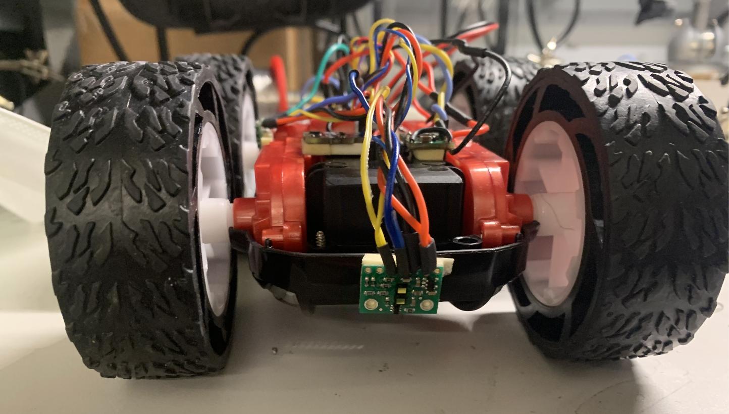
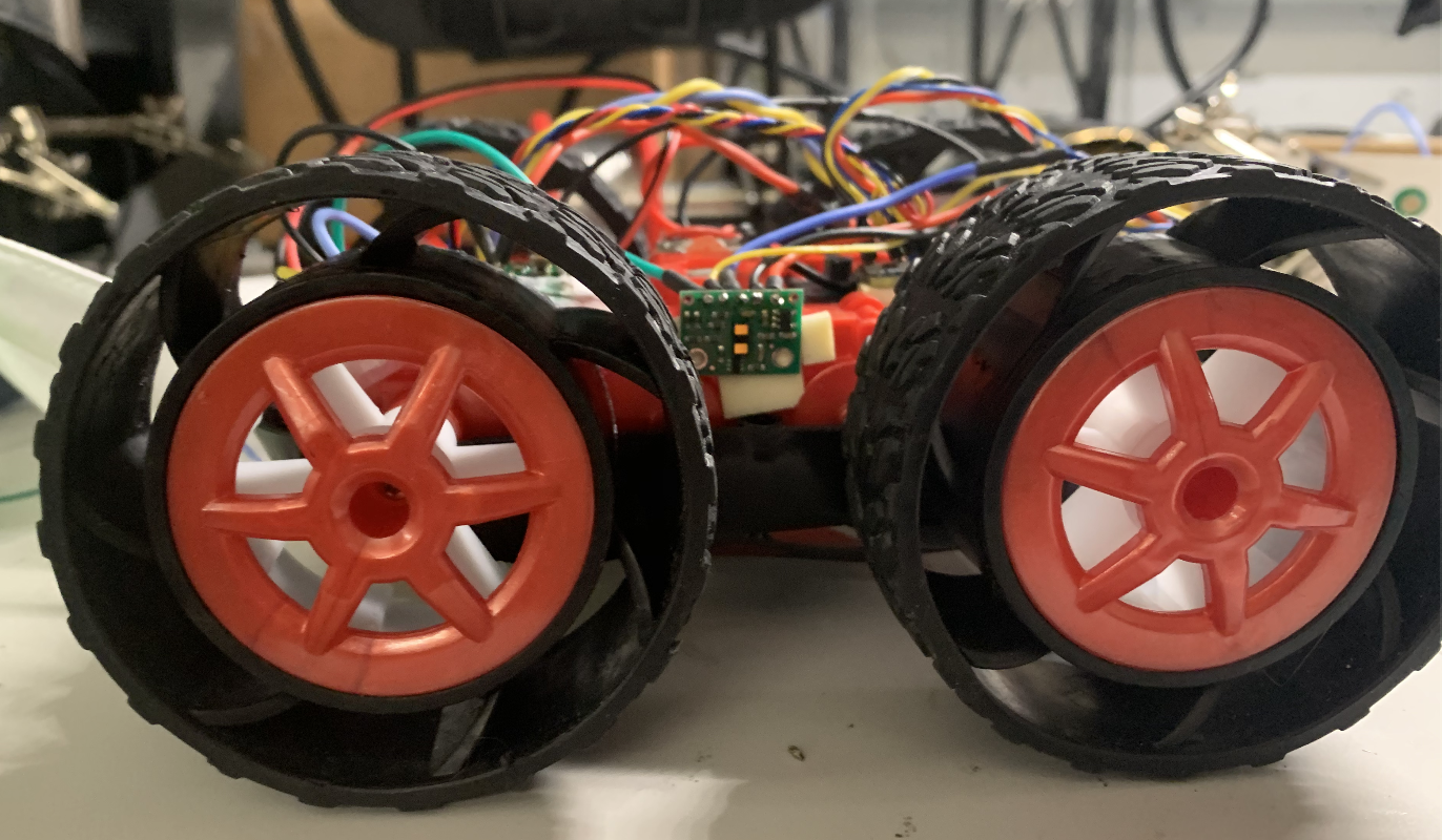
Given below are the final electrical connections in the robot along with the color-coded wires used. I twisted all the wires to reduce noise, used short, stranded wires to make all connections and secured them with heat shrink.

I placed all the components in the car chassis using double sided tape. I placed the Artemis and its battery vertically in the back with the connected pins side on top. There are not glued down to allow programming the board easily. I placed one motor driver and the IMU flat on top of the battery chassis. I added the TOF sensors on the front and the side, such that there are no obstructions in front of it. I placed the other motor driver next to the Artemis.

Driving the Robot
Once the car was assembled, I ran it on the ground and explored different speeds of the car. The car does not move forward for values under 80 in analog write. I found that 100 was a good speed for testing purposes for a fully charged battery.
Moving in a straight line
The right motor was slightly faster than the left motor, so I used a small calibration to allow the motor to travel a straight line. Initially I was using fast decay to break and the motor that was calibrated with higher power ran for a longer than the other motor. This resulted in the car swerving to one side when coming to a stop. I used the slow decay/hard stop mode to overcome this issue.
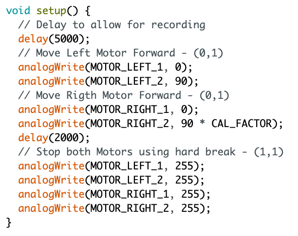
Open loop control
To demonstrate open loop control, I programmed the car to do this sequence (Forward, Right, Forward Right) as shown in the video below. To make a right turn, we need to run the left wheels in forward direction and right wheels in backward direction.
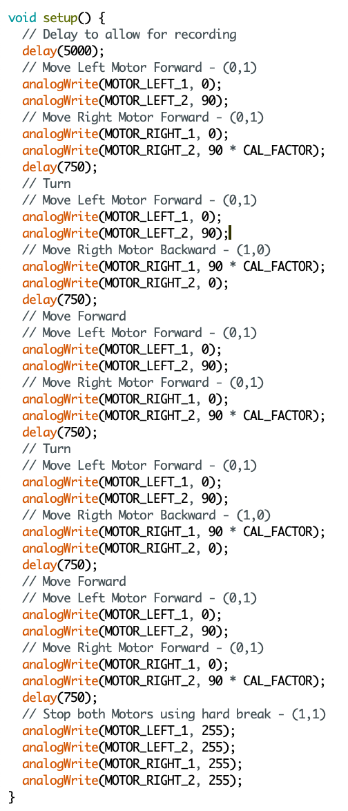
To make a complete 360-degree turn, we need to provide the PWM signals for a longer time. The video below demonstrated is.
Calibrating the robot to move in a straight line and making 90-degree turns was very difficult as the motors’ behavior changes with the battery power. I used a fully powered battery and slow speed for calibration.