Testing and Debugging
Mechanical Aspect
One of the main challenges we faced in this project was refining the design of the strumming arm. It took several iterations to resolve issues related to mechanical noise, instability, and ensuring the arm had the proper range of motion without interfering with the muting components. We also encountered clearance issues with the pick, as it initially couldn’t reach the strings—this required careful adjustments to address positioning and reach. Assembling the servo mounts onto the main mounting plate was also a challenge; it took time to finalize optimal locations for functionality and support.
I wish we had more accurately measured where the servo mounts needed to go beforehand, as the mounting plate took a long time to print—making redesigns and reprints time-consuming. Additionally, the guitar neck is not exactly flat, but rounded. This became apparent when our muting mechanism only effectively muted the top three strings, less so on the bottom strings, because they are positioned vertically lower due to the guitar’s design. We also had to CAD a custom servo mount to ensure the servo stood upright rather than laterally for proper strumming motion.
One thing I wish we had known earlier was the bioacoustic effect of the servo and pick—the vibrations produced a surprisingly loud mechanical noise. Unlike strumming by hand, where your fingers absorb much of the vibration and you mostly hear the strings, the strumming arm amplified both the string and mechanical sounds. Understanding that earlier would have informed our material and design choices for quieter operation. These experiences highlighted the importance of planning for mechanical tolerances, acoustic behavior, and clearance early in the design process.
Electrical/Software Aspect
Pulse-Width Modulation Using Timer/PWM Module
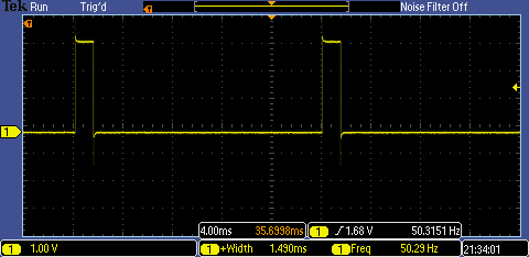
Sending an accurate PWM signal to the servos was a primary goal of this project. To debug the signal, an oscilloscope was hooked up to the PWM signals on pins PTB18/PTB19, measuring the period, frequency, and pulse width. Early on, there were issues deriving the correct clock period for the TPM module, and consequently the PWM signal.
In theory, the external oscillator is more reliable, as the core clock could potentially be affected by CPU processes. Thus, different base clock frequencies were tested with the TPM module, including the core clock and the external 8 MHz crystal oscillator. However, using the external oscillator did not produce any signal. The core clock remained the only viable option.
Initially, TPM had been set up with a 20.97 MHz core clock base and a 128 prescaler, producing tick division values that were not necessarily integers and had low resolution with higher prescalers.
Instead, changing the program to run on a 48 MHz core clock and a 64 prescaler yielded more accurate results, providing a wider range of precise duty cycles and a modulus value of ~15,000 (well under the 16-bit limit of 65,535). However, the actual core clock was running at 47.972352 MHz, so the modulus and CnV values were not exact integers and had to be rounded, slightly reducing accuracy.
Clock frequency changes were made using the clock configuration interface in MCUXpresso IDE. Specifically, the FEI (FLL Engaged Internal) core clock was modified to ~48 MHz. MCUXpresso automatically updates the relevant board code files for internal clock adjustment. With the new board frequency set, more precise PWM signals were achieved for servo motion using the TPM.
Signal Analysis and Servo Testing
The initial MOD value of 14991 (derived from the formula) produced an experimental PWM frequency of 50.3 Hz, which was slightly off. Using the oscilloscope, the frequency and pulse width were measured in real-time, and the MOD value was adjusted via trial and error to achieve a near-perfect 50 Hz frequency, as shown below.
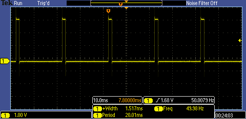
The CnV values were adjusted to correspond to pulse widths between 1–2 ms, which provide the full range of motion for a servo. To simplify angle-to-CnV conversions, the helper function angle_to_CnV(angle) converts angles (0–180°) to CnV values based on the TPM. This function helped fine-tune the strumming angles using a protractor and also defined servo angles for the muting mechanism.
An Arduino program was created to test the servo angle range with linear actuation, using a potentiometer to vary the pulse width. The proper angle for the muting servo was determined experimentally so that the horizontal mute bar dampened the strings enough to produce the desired palm-muting effect.
FSM and Scheduler Testing
As explained earlier, the StrumState struct contains four states: STRUM_DOWN, STRUM_UP, MUTE_ON, and MUTE_OFF. All four were implemented and tested in state_update(), and their respective motions were confirmed by monitoring pulse width changes on the oscilloscope using a timestamp-based scheduler TimeStep.
Later, the StrumStep[] scheduler was created to use note durations instead of timestamps to produce musical patterns. A typical 4/4 strumming pattern was recorded by hand, then encoded into a sequence of strumming steps. The resulting strumming pattern correctly corresponded to servo motions and PWM changes at expected intervals.

The final implementation merged muting and strumming into a single step type: ComboStep. Since each step updates both the strum and mute states simultaneously, muting and strumming have limited independence in this design. For greater flexibility, muting could change independently of strumming by holding the current strum state while modifying the mute state. This would require adjusting the timing of other steps to maintain rhythm integrity. This potential change is discussed in the Future Improvements section and compared to using two independent FSMs.
PIT Interrupts
Originally, we mistakenly assumed that the PIT timer used the full 48 MHz system core clock. As a result, strumming patterns played at half speed—a quarter note at 120 BPM played as if at 60 BPM. Dividing the system core clock by two to reflect the 24 MHz bus clock (used by PIT) corrected the tempo issues.
Support for Multiple Patterns and Button Toggles
With accurate timing established by the PIT scheduler, the next goal was enabling pattern switching and muting via buttons. Buttons connected to port interrupts were used to toggle between patterns and muting states.
Initially, button presses failed due to incorrect wiring to high voltage. Port interrupts trigger on a connection to ground, so the button was rewired with one side to the port and the other to ground. While this fixed the logic, multiple presses were sometimes registered for a single press. A capacitor was added in parallel for debouncing, which reduced—though did not eliminate—the issue. Nevertheless, the buttons functioned as needed for switching between strumming patterns.