Blinking LED
Got the internal LED on the board to blink.
LED on board blinks red.We then tested all digital Pins on the board, starting from 13 and going down to 1. External LED blinks. The following example tests pin 11:
// the setup function runs once when you press reset or power the board
int pin = 11;

void setup() {
  pinMode(pin, OUTPUT);
}

// the loop function runs over and over again forever
void loop() {
  digitalWrite(pin, HIGH);   // turn the LED on (HIGH is the voltage level)
  delay(1000);                       // wait for a second
  digitalWrite(pin, LOW);    // turn the LED off by making the voltage LOW
  delay(1000);                       // wait for a second
}
LED in digital pin #1 blinks.
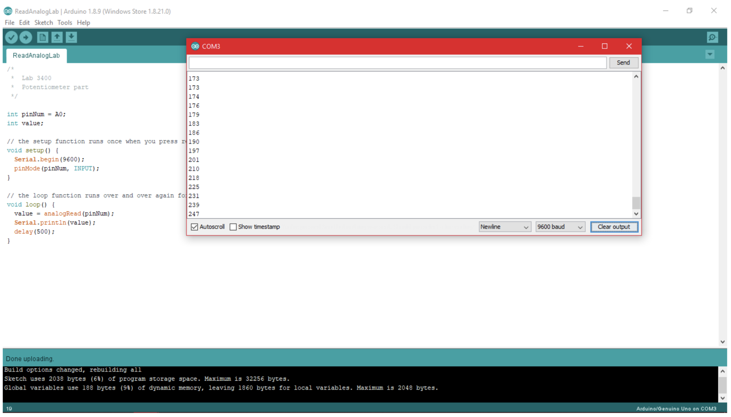
Potentiometer
Put potentiometer in a simple voltage divider and used DMM to measure the variable resistance (on order of kΩ).
int pinNum = A5;
int value;

// the setup function runs once when you press reset or power the board
void setup() {
  Serial.begin(9600);
  pinMode(pinNum, INPUT);
}

// the loop function runs over and over again forever
void loop() {
  value = analogRead(pinNum);
  Serial.println(value);
  delay(500);
}
- Used a 32.7kΩ in the voltage divider, expected 1.3V across divider
- Tested all analog pins
- Read a high of 658 and low of 0
 Potentiometer output varies as we moved the wiper.
We then used the potentiometer to implement PWM, which controlled the brightness of the LED.
int pinNum = A5;
int ledPin = 3;
float value;

// the setup function runs once when you press reset or power the board
void setup() {
  Serial.begin(9600);
  pinMode(pinNum, INPUT);
  pinMode(ledPin, OUTPUT);
}

// the loop function runs over and over again forever
void loop() {
  value = analogRead(pinNum);
  analogWrite(ledPin,round((value/658)*255));
  Serial.println((value/658)*255);
  delay(500);
}
LED brightness changes due to potentiometer.
We also used the potentiometer to control speed and direction of a servo.
#includeSpeed and direction of servo changes due to potentiometer.Servo myServo; int pinNum = A5; int value; // the setup function runs once when you press reset or power the board void setup() { Serial.begin(9600); myServo.attach(3); pinMode(pinNum, INPUT); } // the loop function runs over and over again forever void loop() { value = analogRead(pinNum); Serial.println(value); value = map(value, 154, 658, 0, 180); myServo.write(value); delay(500); }
Building the Robot
Using these systems, we assembled the robot.
Components of the Robot:
- 1 Plastic chasis
- 2 Servo holders
- 2 Servos
- 2 Wheels w/ treads
- 1 Battery pack
- 1 Ball bearing
- 1 Breadboard
- 1 Arduino
- Wires and screws
We programmed the robot to drive in a square path.
#includeRobot drives in a square path.Servo myServo1; Servo myServo2; int servoSpeed1 = 0; int servoSpeed2 = 180; int i; // the setup function runs once when you press reset or power the board void setup() { Serial.begin(9600); myServo1.attach(3); myServo2.attach(5); } //robot moves straight void straight(){ myServo1.write(servoSpeed1); myServo2.write(servoSpeed2); } void turnRight(){ myServo1.write(servoSpeed2); myServo2.write(servoSpeed2); } void turnLeft(){ myServo1.write(servoSpeed1); myServo2.write(servoSpeed1); } void rightSquare(){ for(i=0; i<4; i++){ turnRight(); delay(630); straight(); delay(2000); } } void leftSquare(){ for(i=0; i<4; i++){ turnLeft(); delay(630); straight(); delay(2000); } } // the loop function runs over and over again forever void loop() { rightSquare(); leftSquare(); }