Objective
The objective of Lab 2 was to add two additional circuits to the robot. By the end of the lab, we should have a microphone circuit that detects a tone of 950 Hz to signify the beginning of the race and another sensing circuit of our choice. We chose a Schmitt trigger circuit.
Materials
- 1 Electret Microphone
- 1 LM358p Op Amps
- 2 LM471N Op Amps
- 1 White LED
- Breadboard
- Capacitors
- Wires
- Resistors
Prelab
We downloaded the Open Music Labs FFT Library for Arduino and modifed the code to detect 950 Hz. We know that the sample code provided for the FFT is going to compute a 256 Bin FFT. For our code, we needed 950Hzx2 = 1900Hz based on the Nyquist Sampling rate to avoid aliasing. AnalogRead, according to online documentation, can sample at a rate of 9600 Hz. Therefore, during the prelab, we decided to use analogRead() for the microphone circuit. Since 9600/256 = 37.5 Hz, we predicted that the 950 Hz frequency should be in approximately the 25th bin. Realistically, the rate of analogRead was lower and through printing out the fft values, we saw that the actual bin is at 27.
However, during the lab, when trying to incorporate the code together, we were facing issues with calibrating our servos. We realized that the cause of this issue was that the fft code causes our environment to switch to a free running counter mode. However, the rest of the code works on clocked cycles. So, our code was behaving unexpectedly due to this discrepancy. To fix the issues with the clock, we saved and reassigned the required values at the beginning and end of the fft code. We also noticed how, sometimes, the microphone wasn't detecting the tone quickly enough. Therefore, we decided to experiment with the adc pin. So, we had to redo our calculations to make sure that the bin number was still similar. The Arduino Uno clock speed is 16 MHz. The adc clock, therefore, is set to 16 MHz/128 = 125 KHz. Each conversion in AVR takes 13 ADC clocks so 125 KHz /13 = 9615 Hz. 9615 / 256 = ~ 37.5 Hz. So, the adc pin had a relatively higher sampling rate and we found that the bin number was now 25.
Lab
Microphone Circuit
We first built the microphone circuit. The circuit diagram, provided in the lab documentation, is below:
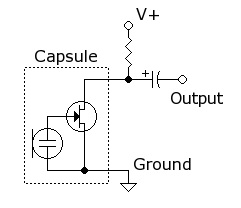 Microphone circuit diagram from Lab Documentation
Many microphones were blown, so we had to test a lot before we found a decent microphone. Even after that, the signal we were receiving was very weak and didn't really show up on the oscilloscope.
Since our signal was so weak, we realized that we needed to add an amplifier to amplify the signal. As per the recommendation given in class, we used Team Alpha's design for an inverting amplifier. In this amplifier circuit, the input signal goes into the inverting terminal of a LM741N op amp, with a 3.8k resistor in series and a 380k resistor on the feedback loop. This creates a gain of 100 on the signal we input. On the non inverting terminal, we created a voltage divider from two 10k resistors, between 5V Vdd and ground. This creates a virtual ground at 2.5 V, and will bias our output signal to center around 2.5 V. This will allow us to center the signal between the rails of 5V and ground, and allow us to use the maximum range of the amplifier. The circuit is shown below:
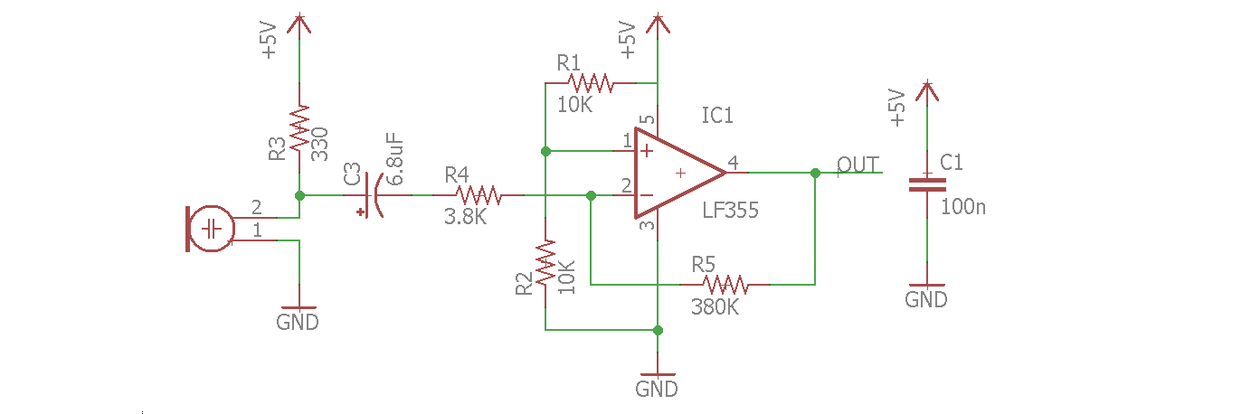 Team Alpha's amplifier circuit from their website
 Our implementation of Team Alpha's amplifier circuit
The amplifier was successfully able to amplify the weaker, blue signal, and create the yellow signal as shown in the oscilloscope reading below.
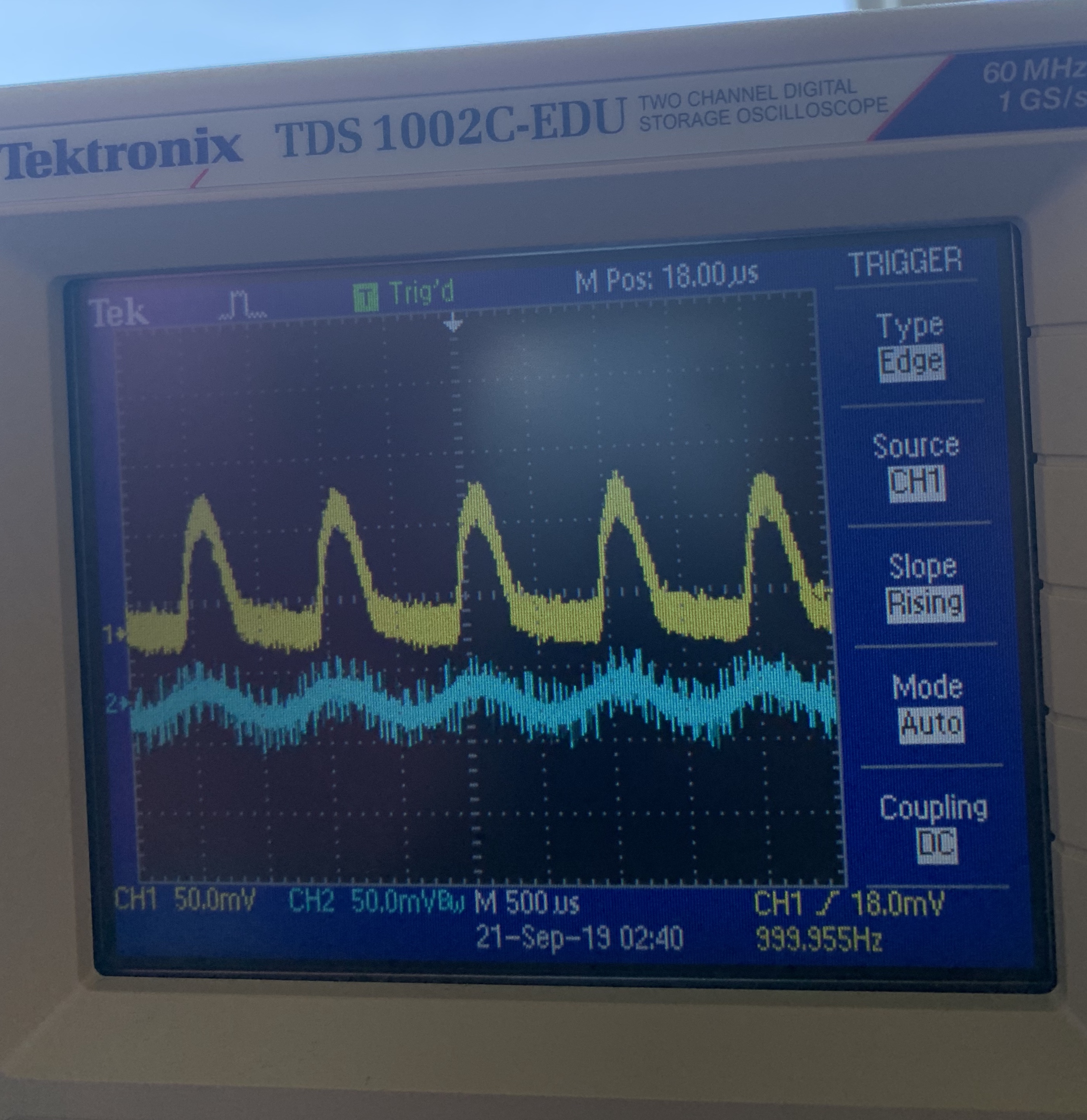 Oscilloscope reading of amplifier
Once we added the amplifier, we were able to see the signal well on the oscilloscope as seen above. To improve the performance of our circuit when detecting 950 Hz, we decided to add a bandpass filter to the output of the amplifier. We chose to first amplify and then filter since the initial signal was very weak.
The passive band pass filter is a high pass and a low pass filter in series. The low pass filter is set with a -3dB threshold of 1068Hz, while the high pass filter is set with a -3dB threshold of 905 Hz. A circuit diagram of the filter is shown below.
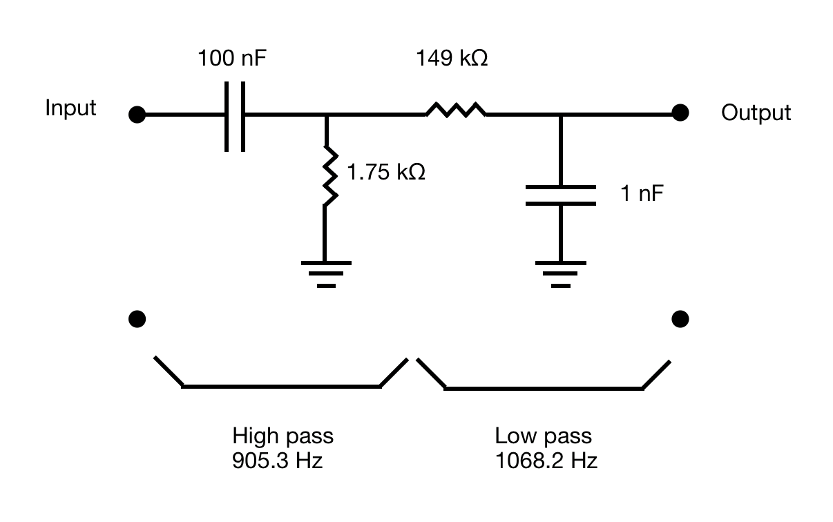 Circuit diagram of the bandpass filter
We then tested the filter using the oscilloscope to ensure that it was working correctly. We have added pictures showing our signal before and after using the filter below.
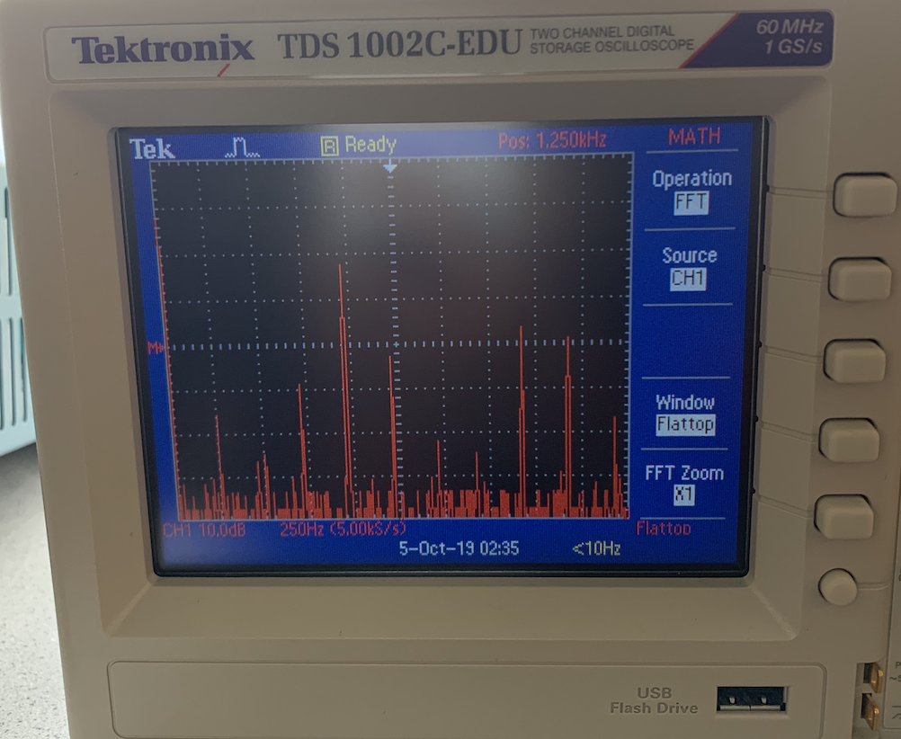
 Output signal before using filter
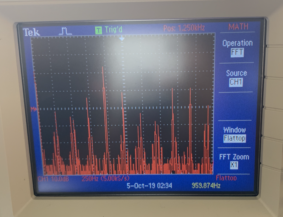
 Output signal after using bandpass filter.
Highest peak is 950Hz.
Output signal after using bandpass filter.
Highest peak is 950Hz.
Finally, we verified that our microphone circuit works using the fft code from the fft library. We demonstrate how our microphone only detects signals very close to 950 Hz below.
The Arduino detects when a tone is played at 950 HzWe then integrated the microphone circuit with out robot. Below, we demostrate how the robot waits to hear 950Hz to begin moving.
Robot starts moving after hearing 950Hz tone.In the event that our microphone circuit doesn't work unexpectedly during the competition, we also added a push button to our robot as an alternative to signal the robot to begin the race. We connected one pin of the push button to ground, one to voltage and one to pin 7. As seen below, the push button sends a HIGH signal when it is released and a LOW signal when it is pressed.
 Circuit for push button
Printing the value of the push button press
Circuit for push button
Printing the value of the push button press
We then incorporated the push button onto the robot too. A demo is shown below:
Robot moves when push button is pressedThe code integrating everything together is provided below:
#define LOG_OUT 1 // use the log output function #define FFT_N 256 // set to 256 point fft #include#include // include the library Servo rightServo; // right Servo leftServo; // left int speed1 = 85; int speed2 = 95; int speedStop = 90; int inPin = 7; // choose the input pin (for a pushbutton) int pushV = 1; // variable for reading the pin status int fftV = 0; // variable for checking if 950 hz was found unsigned int timsko = 0; unsigned int admux = 0; unsigned int didro = 0; unsigned int adcsra = 0; void straight(){ rightServo.write(speed1); leftServo.write(speed2); } void servoStop(){ rightServo.write(speedStop); leftServo.write(speedStop); delay(50); } void setup() { pinMode(inPin, INPUT); // declare pushbutton as input rightServo.attach(5); leftServo.attach(3); timsko = TIMSK0; admux = ADMUX; didro = DIDR0; adcsra = ADCSRA; while (pushV == 1 && fftV == 0) { pushV = digitalRead(inPin); servoStop(); fft(); } } void fft() { TIMSK0 = 0; ADCSRA = 0xe5; // adc4 ADMUX = 0x44; DIDR0 = 0x04; cli(); // UDRE interrupt slows this way down on arduino1.0 for (int i = 0 ; i < 512 ; i += 2) { // save 256 samples while(!(ADCSRA & 0x10)); // wait for adc to be ready ADCSRA = 0xf5; // restart adc byte m = ADCL; // fetch adc data byte j = ADCH; int k = (j << 8) | m; k -= 0x0200; k <<= 6; fft_input[i] = k; // put real data into even bins fft_input[i+1] = 0; // set odd bins to 0 } // window data, then reorder, then run, then take output fft_window(); // window the data for better frequency response fft_reorder(); // reorder the data before doing the fft fft_run(); // process the data in the fft fft_mag_log(); // take the output of the fft sei(); // turn interrupts back on String bin = "Bin Number "; String sp = ": "; //check a range in case the clock cycle makes the bin number different for (int i = 23; i < 27; i++) { if (fft_log_out[i] >= 50){ // check that bin 25 has our 950hz frequency fftV = 1; } } TIMSK0 = timsko; ADMUX = admux; DIDR0 = didro; ADCSRA = adcsra; } void loop(){ straight(); }
Schmitt Trigger
Looking ahead, we realized that we wanted to add three more IR sensors for detecting walls and overall, solving the maze, but the line sensors were taking up 3 analog pins and the IR sensors would take up another 3 analog pins. We only have 6 analog pins, and the microphone also requires an analog pin. So, we decided to implement a Schmitt Trigger circuit to free up some analog pins and convert the analog input from the line sensors into digital outputs.
Intuition: A Schmitt Trigger is a comparator that goes high if you are above a certain upper threshold voltage and goes low if you are below a certain lower threshold. As a result, we can send the output of the trigger to a digital pin and free up three analog pins. Our schmitt trigger design uses a voltage divider on the non inverting terminal, as well as a feedback loop on the non inverting terminal. When the output is high, the voltage divider changes so the comparison threshold is 5k||10k over 3.3k. When the output is low, the output is 5k over 10k||3.3k. This design moves the threshold for the op amp comparator whenever the output changes state, removing any oscillations due to noise. Our line sensor detected ~3V when white, and ~1V when dark, so we set our upper voltage to be 2.4V, and our lower threshold to be 1.6V. The readings from the line sensor is our input to the circuit, which is shown below:
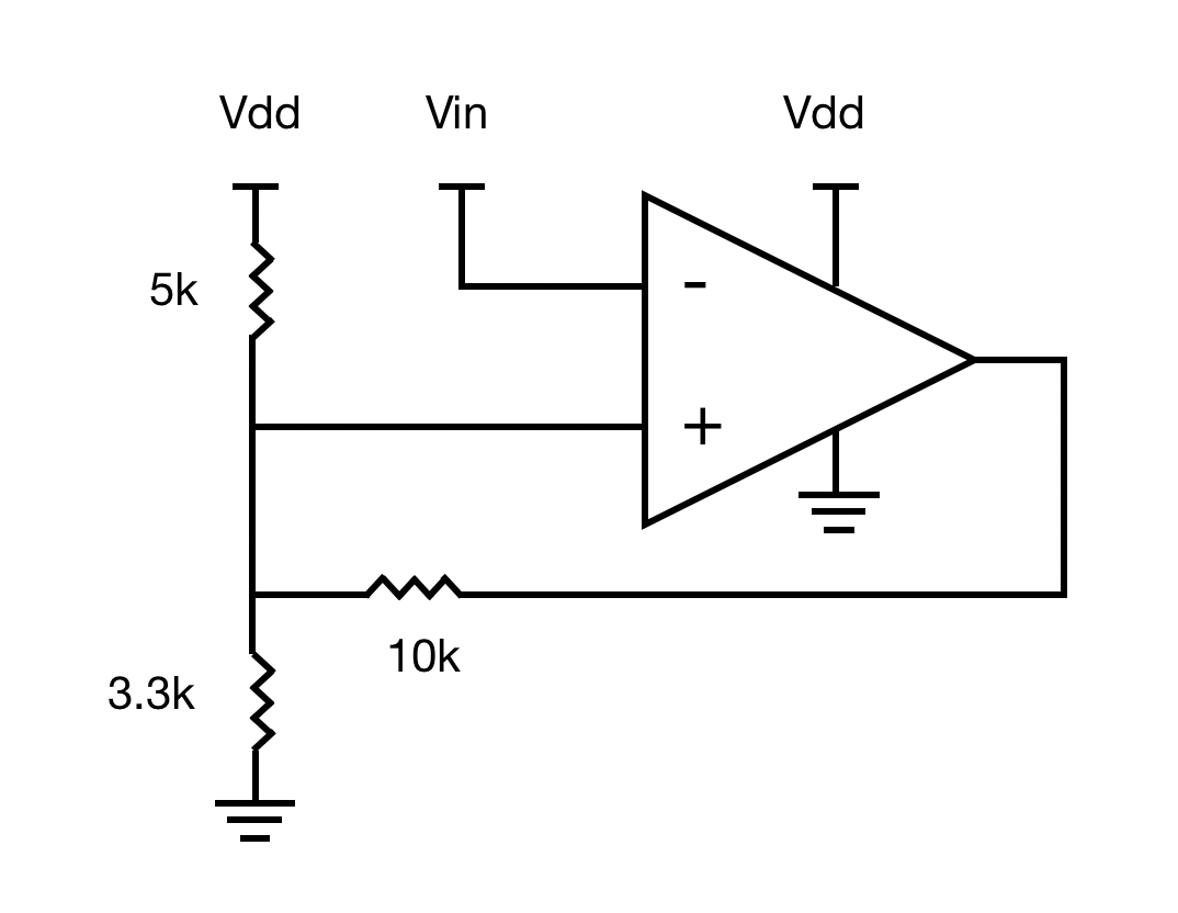 Circuit diagram of the Schmitt Trigger
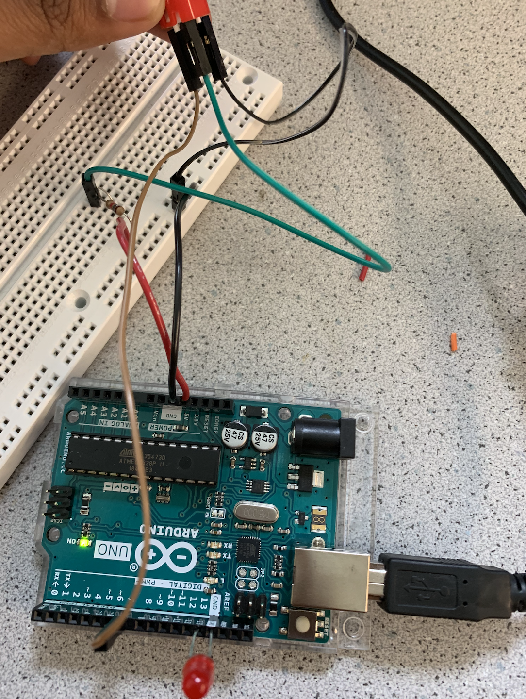
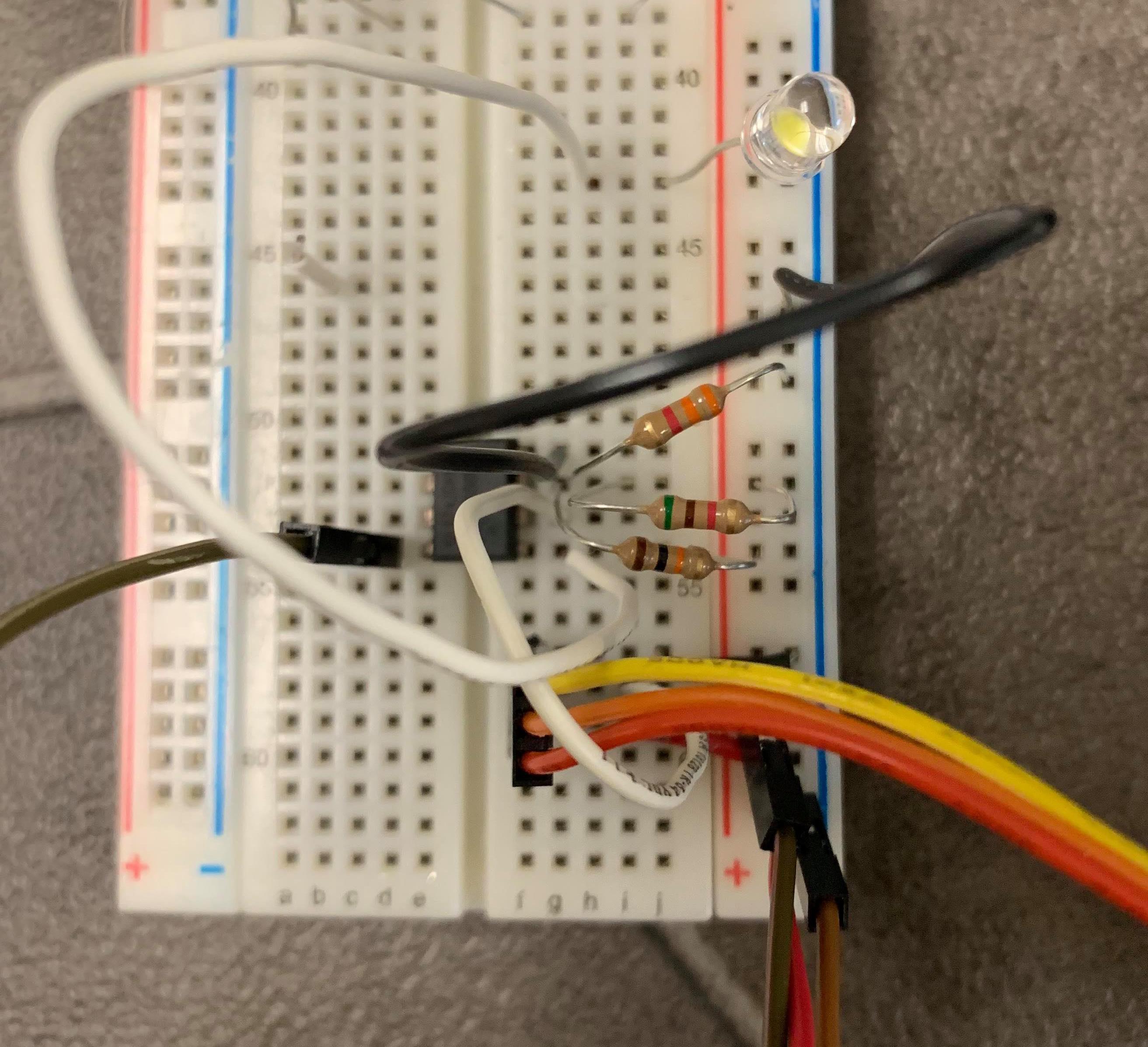 Our implementation of the schmitt trigger
We used two equations to figure out the resistor values: Vs = (R3 / (R3 + R1||R2)) * Vref - Vth and Vs = ((R2||R3) / (R1 + R2||R3)) * Vref + Vth. We set R2 to 10kOhms, Vref is Vdd which is set to 5 V, Vs is set to 2V and Vth to 0.4V. We then found R1 to be 5kOhms and R3 to be 3.3kOhms respectively. We used the LM358p Op Amp for the trigger. After that, we tested the trigger on the black and white floor. Below, we demonstrate how, when the line sensor moves over the white tape, the white LED light ups, signalling that white was detected and the turns off when it detects black.
The Arduino detects when it sees white and turns on LEDWe have added the code we used to test the trigger below. The trigger will be added to the robot for Milestone 2.
  int inPin = 2;    // pushbutton connected to digital pin 7
  int val = 0;      // variable to store the read value

  void setup() {
    pinMode(inPin, INPUT);    // sets the digital pin 7 as input
    Serial.begin(9600);
  }

  void loop() {
    val = digitalRead(inPin);   // read the input pin
    Serial.println(val);
  }