Objective
In preparation for the final competition, the robot should be able to send relevant data to the base station via radio. Once the data is received at the base station, the FPGA should display the correct maze information as the robot traverses the maze. Robot detection should also be successfully integrated into DFS. The final step is to integrate FFT code, radio, robot detction and DFS together.
Materials
- 2 nRF24L01+ transceivers
- 2 radio breakout boards with headers
- 2 Arduino Unos
- 1 DE0-Nano FPGA Board
Radio Commmunication
What Information is Sent?
Our radios communicate 7 bits of information:
- We have two bits for direction the robot is heading (00 - North, 01 - East, 10 - South, and 11 - West). The most significant bit we call "DIR_M" and the least significant bit is "DIR_L".
- Four bits for walls once the robot turns in the direction it will head towards. "WALL_FRONT" will be high if there is a wall in front, and low if a wall is not present in front of the robot. Likewise, similar signals exist "WALL_RIGHT", "WALL_LEFT", and "WALL_BACK" for the presence of right, left, and back walls.
- Note that we have a back wall bit because once we turn, there may be a back wall behind us. This wall sensor is not used for DFS.
- We also have one update bit, "UPDATE" which will be high when we send new and valid information. This happens only at an intersection and is immediately reset to 0 on the next iteration of the loop() function in the robot arduino code.
Transmitter & Receiver Code
We had two radios - one connected to the robot and the other connected to the base station. We made the radio connected to the robot the transmitter - i.e sends information, and the radio connected to the base station the receiver. Our first step was to make sure our radios worked. To do that, we send hardcoded information from one radio to the other. We had to use bigger channels instead of the recommended ones to cancel noise. So, our channels were 0x0000004600LL and 0x0000004700LL. After ensuring that the radios work, we wrote specific transmitter and receiver code.
The transmitter code works through the following steps:
- In the setup stage, we set the required fields for the radio as seen below in the code.
- Within the loop, the transmitter radio stops listening and sends information out. The information sent is discussed above. Then, it starts listening again.
            void setup(void)
{
  radio.begin();

  // optionally, increase the delay between retries & # of retries
  radio.setRetries(15,15);
  radio.setAutoAck(true);
  // set the channel
  radio.setChannel(0x50);
  // set the power
  // RF24_PA_MIN=-18dBm, RF24_PA_LOW=-12dBm, RF24_PA_MED=-6dBM, and RF24_PA_HIGH=0dBm.
  radio.setPALevel(RF24_PA_MIN);
  //RF24_250KBPS for 250kbs, RF24_1MBPS for 1Mbps, or RF24_2MBPS for 2Mbps
  radio.setDataRate(RF24_250KBPS);

  radio.openWritingPipe(pipes[0]);
  radio.openReadingPipe(1,pipes[1]);
  radio.startListening();
}

void loop(void)
{
    // First, stop listening so we can talk.
    radio.stopListening();

    // Take the time, and send it.  This will block until complete
    byte val = 0b00000010; //will set correct values when integrating
    bool ok = radio.write( &val, sizeof(byte) );

    // Now, continue listening
    radio.startListening();
}
Once our receiver code extracts the message that was transmitted. We break up that message via bit masking into the 7 bits described earlier. For example, to determine if we received an update (stored in update_bit), we bit-wise and the message (got_val) with 01000000. We then turn our update_bit into a one bit value by determining if that bit-wise operation resulted in all zeros in which case no update was received; otherwise, an update was received.
    // do bit masking
    int update_bit = ((got_val & 0b01000000) == 0)? 0 : 1;
    int dir_M =      ((got_val & 0b00100000) == 0)? 0 : 1;
    int dir_L =      ((got_val & 0b00010000) == 0)? 0 : 1;
    int wall_F =     ((got_val & 0b00001000) == 0)? 0 : 1;
    int wall_R =     ((got_val & 0b00000100) == 0)? 0 : 1;
    int wall_L =     ((got_val & 0b00000010) == 0)? 0 : 1;
    int robot_bit =  ((got_val & 0b00000001) == 0)? 0 : 1;
Bit masking as shown above determines what we send to the FPGA. For example, if there was an update, we set our digital output high for the digital output pin corresponding to the update.
    // sending values to FPGA
    if(update_bit){
      digitalWrite(8, HIGH);
    }
    else{
      digitalWrite(8, LOW);
    }
The receiver code checks to see if there is any information available to read. If so, the data is read and stored in a variable. We then bitmask as discussed above to figure out what signals to send to the digital pins on the arduino. The following video shows how we tested that the transmitter/receiver code is working after the final integration with DFS:
Serial monitor on the receiver side, where it is only printing information (direction and walls) when update is high. Corresponding video of robot moving as it sends radio information.Base Station Display
Our base station display is a 270x270 pixel grid, where each "tile" is a 30x30 pixel square on our grid. Since our DFS defines the North and East direction as positive, we start drawing the mase in the bottom left of the 270x270 area. We programmed the FPGA to draw only the tile we are currently on by turning on the write enable for those pixels. In this way, we cycle through all the pixels of the grid repeatedly, however only the pixels enabled by our write enable will be written to memory and displayed on the monitor. Additionally, since we only draw the tiles that the robot sees, any tiles that are unreachable will simply show up as part of the background with the correct walls enclosing it. The structure of our verilog code is discussed in detail for lab 3.
When information is sent from the base station Arduino to the FPGA:
As mentioned earlier, an update bit, direction bits, and wall bits are constantly being sent over radio to the base station Arduino from the robot. However, on the base station side, we really only care about when the update bit goes high. This means that we arrived at an intersection and now have the direction we want to go to. Thus, it is at the posedge of UDPATE that we increment/decrement our position according to the direction we are going to go. We then use these coordinates to process the wall and direction information to store to the walls array accordingly and then write the resulting tile to the screen.
Sending information from base station Arduino to FPGA
When the Arduino recieves information via radio from the robot, we access the individual bits of the sent data and set those as outputs on the arduino. As described in Lab 3, we use parallel communication between this base station Arduino and FPGA. The output bits from the Arduino are connected to GPIO 1 pins 14, 16, 18, 20, 22, 24, and 26 on the FPGA, and we send those signals into our image processor. These pins correspond to the UPDATE, DIR_M, DIR_L, WALL_FRONT, WALL_RIGHT, WALL_LEFT, WALL_BACK bits from the Arduino respectively.
Representing Accurate Information on Display
After thorough testing, we are confident that we are successfully able to draw what the robot sees correctly. At first, we tested this by simulating robot data with the Arduino, hard-coding values for the walls and direction to create a path the robot would follow. We then moved onto testing the robot in an actual maze, where we encountered some issues. At this point, since we were sending the direction we wanted to go to but the walls relative to our current direction, we realized it would be easier to send the walls relative to the direction we wanted to go in. As a result, we added another back sensor and sent another bit over from the Arduino.
Since we are sending the front, back, right, and left walls relative to our direction, we had to also convert these wall placements into cardinal directions. We had a large case statement that takes in the direction we want to go and the corresponding walls and sets a 2-D array for the walls at the robot's current position. Below is an example case statement, where "walls" is the aforementioned 2-D array for walls:
 case({DIR_M, DIR_L, WALL_FRONT, WALL_RIGHT, WALL_LEFT, WALL_BACK})
    6'b010011 : walls[X][Y] = 4'b1001;
Here, the walls array stores walls as NSEW, so in this example we are going east and we detect walls to the left and back of us. This translates to walls to the North and West.
Some math was also required to figure out the correct range of pixels to draw for the walls, tiles, and grid lines. We draw the border of the maze by using the extreme values of grid (0,1 and 269,270 such that the line is 2 pixels wide). The tiles are 30x30 squares, so we draw the tiles based on the X and Y position of the robot multiplied by 30. The grid lines are drawn when the (pixel address on the screen % 30) - 15 = 0 so that it occurs in the middle of a given tile. For drawing the walls, we bit mask to isolate a given wall in an element of the wall array and calculate the range of X and Y addresses on the screen to draw accordingly. Overall, the walls are red (including the border), the tiles are white, and the grid lines are purple. As mentioned before, any unvisited tile will appear as part of the black background.
Videos & Code
In the first video, we simulated with Arduino code (using digital writes and delays) the signals received via the radio and sent to FPGA. Our robot moves North, but then detects a robot and moves East. Then it moves North again, then West, then North. When the robot moves West, it moves over the tile the robot had been seen earlier, so a robot is drawn on that square. This pattern repeats itself in the video. We later removed robot displaying since it was declared that we should not display robots.
Below is an example of our simulated Arduino code that says our robot is going North and there are no walls or robots (see radio communication section for what each signal means).
  delay(1000);
  digitalWrite(updated, HIGH);
  digitalWrite(dirM, LOW);
  digitalWrite(dirL, LOW);
  digitalWrite(wallF, LOW);
  digitalWrite(wallR, LOW);
  digitalWrite(wallL, LOW);
  digitalWrite(robot, LOW);
  digitalWrite(updated, LOW);
We then moved on to actual radio data from the robot. We first tested the robot in a maze where the first direction it wants to go to is North. The code used is the transmiter and receiver code discussed previously.
We then tested a maze in which the first direction the robot wants to go in is East. We do not need to test West or South as those directions would not be possible at the robot's starting position.
Robot Integration
Storing Maze Information on Arduino
We store information about visited nodes in an array that holds a boolean value, indicating if the node/intersection has been visited. We also have an array that holds backtracking values, so that our robot comes to an intersection, and would like to backtrack, the robot knows which direction to go.
Our x and y position in the maze are stored in the global variables "xcounter" and "ycounter". Our direction is stored in the global variable "dir".
Our finishing logic, which is described in more detail in the green LED section, requires an integer of how many nodes have been seen, a maze_size of how many nodes should be seen, and a done_flag to trigger the green LED turning on.
//general maze
boolean visited[9][9]; // true if this position has been seen, otherwise false
int backptrs[9][9]; // holds direction to move in when backtracking
int backval = 0; // backtrack value to put in array
int walls[3];
boolean isIntersection;

//direction & position
int dir = 0; // direction of robot: 0 - N, 1 - E, 2 - S, 3 - W
int xcounter = 0; // our current x position
int ycounter = 0; // our current y position

//done logic
int num_nodes = 0;
boolean doneFlag = 0;
int maze_size = 81;
Robot can sense other robots and avoid them within implemented navigation algorithm
The robot detection is the same as in Milestone 3, where a phototransistor is attached to a voltage divider. The main difference between the Milestone 3 sensor and current sensor is the phototransistor we used, since the new phototransistor has a smaller viewing angle, which reduces on the amount of light interference. The main trial we worked on was figuring out how to detect robots due to outside light intereference. This was aleviated by the competition having blackout curtains and the weather being cloudy, which provided even lighting. Overall, this circuit worked well as we could tune our robot detection on the day of, due to having more analog pins available at our disposal.
As seen in our video below, our robot is able to successfully detect robots and avoid them. In our DFS algorithm, two possible scenarios occur for how to integrate robot detection into our algorithm
1. The robot wants to go in the direction of the other robot, but there is another unexplored direction our robot can go instead. Our robot goes the other direction, and our DFS code will have the robot backtrack to the intersection where it saw the robot, and then go in the direction the other robot previously blocked.
2. The robot wants to go in the direction of the other robot, but there are no unexplored directions the robot can go. To avoid leaving this intersection and backtracking, and therefore leaving this intersection with no way to get back to it (we only moved to unvisited nodes), we mark the node we are at as unvisted before going in a different direction than the robot.
We make sure to detect robots both when moving forward and when backtracking.
Green LED on robot to signal end of mapping/exploring
As seen in the video below, the robot will turn on the green LED when it has finished mapping the maze. Our robot knows it has finished the maze when one of two conditions occur.
1. The robot has seen all 81 intersections, so it turns on the green LED and makes its way back to the start.
2. The robot has backtracked all the way to the start. And now that it's back at the start, it sees no unexplored ways to go. Therefore, the robot knows it is done, turns on the green LED, and stops.
Start with push button, avoid other robots and turn on Green LED upon completion. Our other robot in this case is an IR Emitter connected to a batter source on a breadboard.Working Override button
Our override button was added in lab 2 and is discussed in detail there. We connected one pin of the push button to ground, one to voltage and one to pin 6. As seen below, the push button sends a HIGH signal when it is released and a LOW signal when it is pressed.
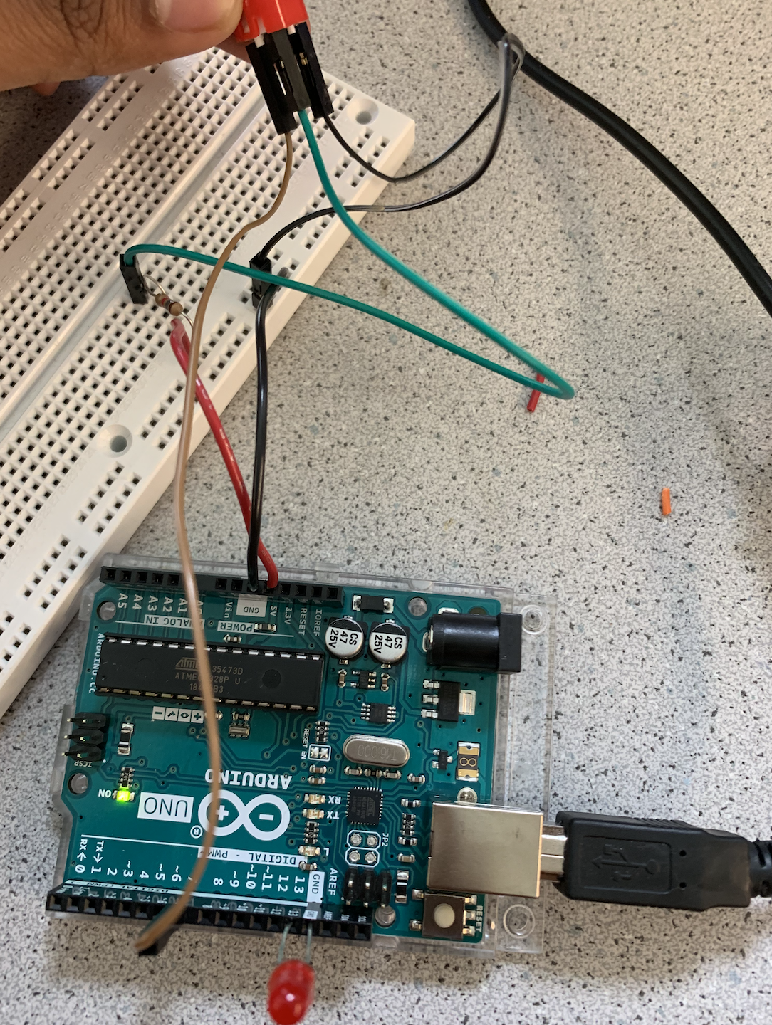 Circuit for push button
Printing the value of the push button press
Circuit for push button
Printing the value of the push button press
Wall sensing operational
Our wall sensing is described in detail in our Milestone 3 page. The three front, right, and left sensors did not change in hardware or code from that page. However, we did add a fourth wall sensor to detect walls behind us. This wall sensor was not used by our maze exploration algorithm, but was sent via the radios to our base station. The motivation behind this is described in the Base Station Display section above.
Our DFS is iterative (not recursive) and does not require a stack, just two arrays. This is an efficient way of storing maze information and implementing a (modified for robot detection) depth first search algorithm. For more detail about our navigation algorithm, see our milestone 3 where the algorithm is discussed in depth with videos, images, and code samples.
Switching to the FHT library instead of the FFT library
Since the FFT library was taking up over 60% of dynamic memory, we researched a bit and switched to the FHT library which performed very similarly but took up only 35% of dynamic memory. A video of our microphone working with the FHT code is shown below: