Intelligent-Physical-Systems
Project maintained by jim59 Hosted on GitHub Pages — Theme by mattgraham
Lab 2
For this lab we were able to build a simple infrared (IR) light detection circuit with three phototransistors on BotMobile & a display component of the base station on a separate breadboard
Accomplishment: BotMobile can now detect IR light using phototransistors -> will later be used to detect treasures which consist of IR LEDs that are positioned randomly in the maze and are blinking at some frequency.
Phase I
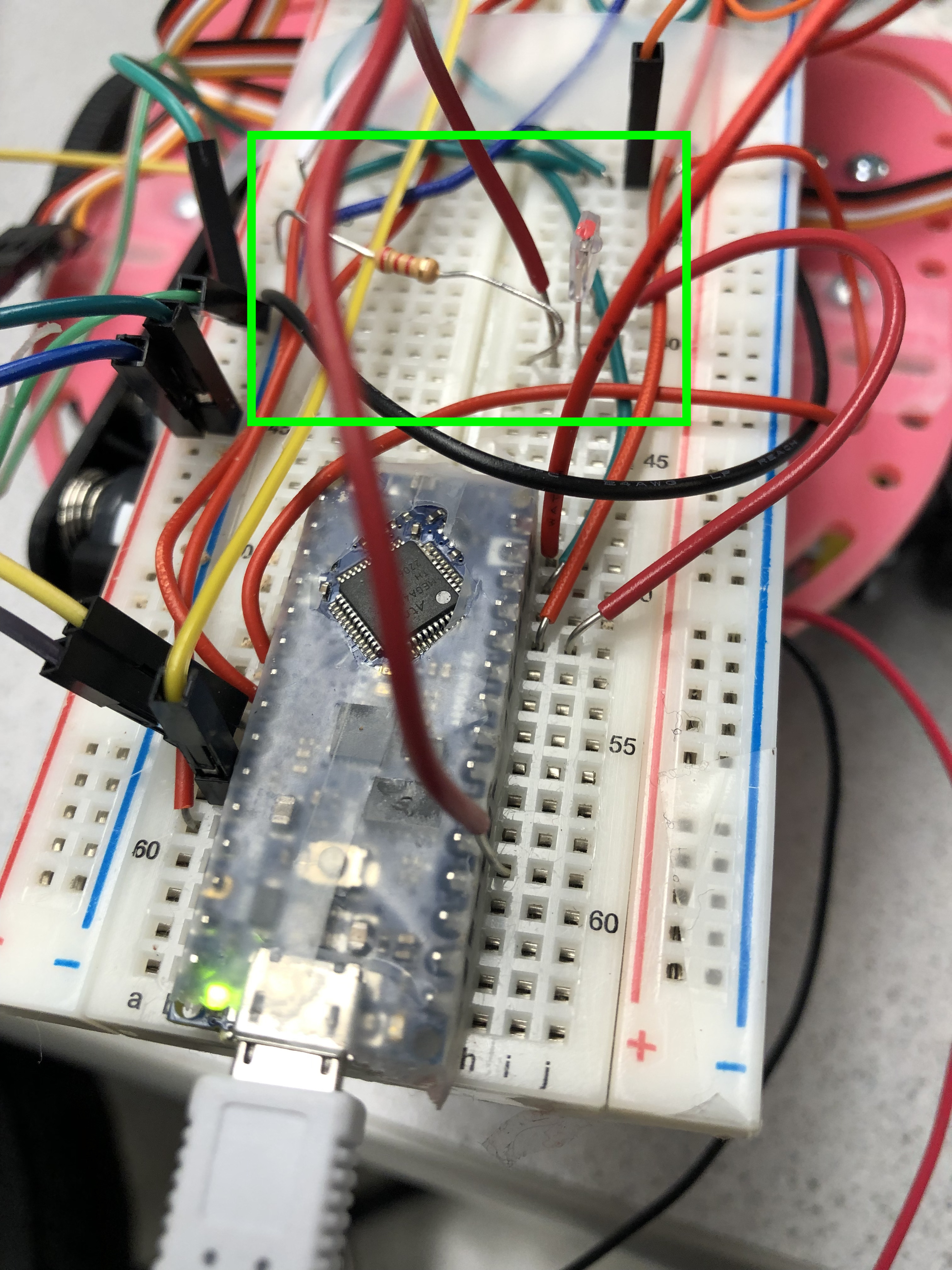
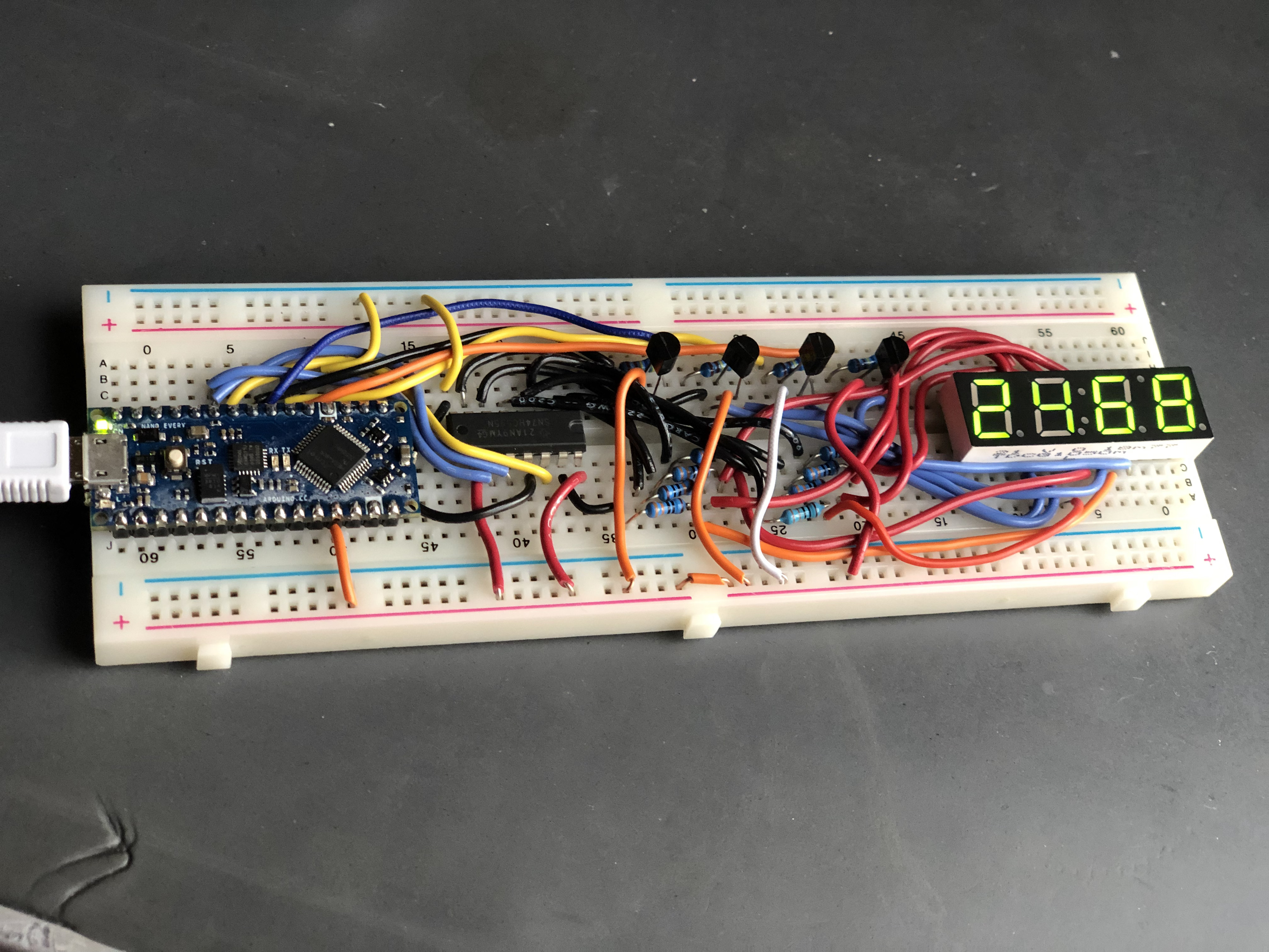
For the first phase of this lab, we built a circuit used to measure voltage on a phototransistor on the main robot breadboard as shown in green box on the image below.
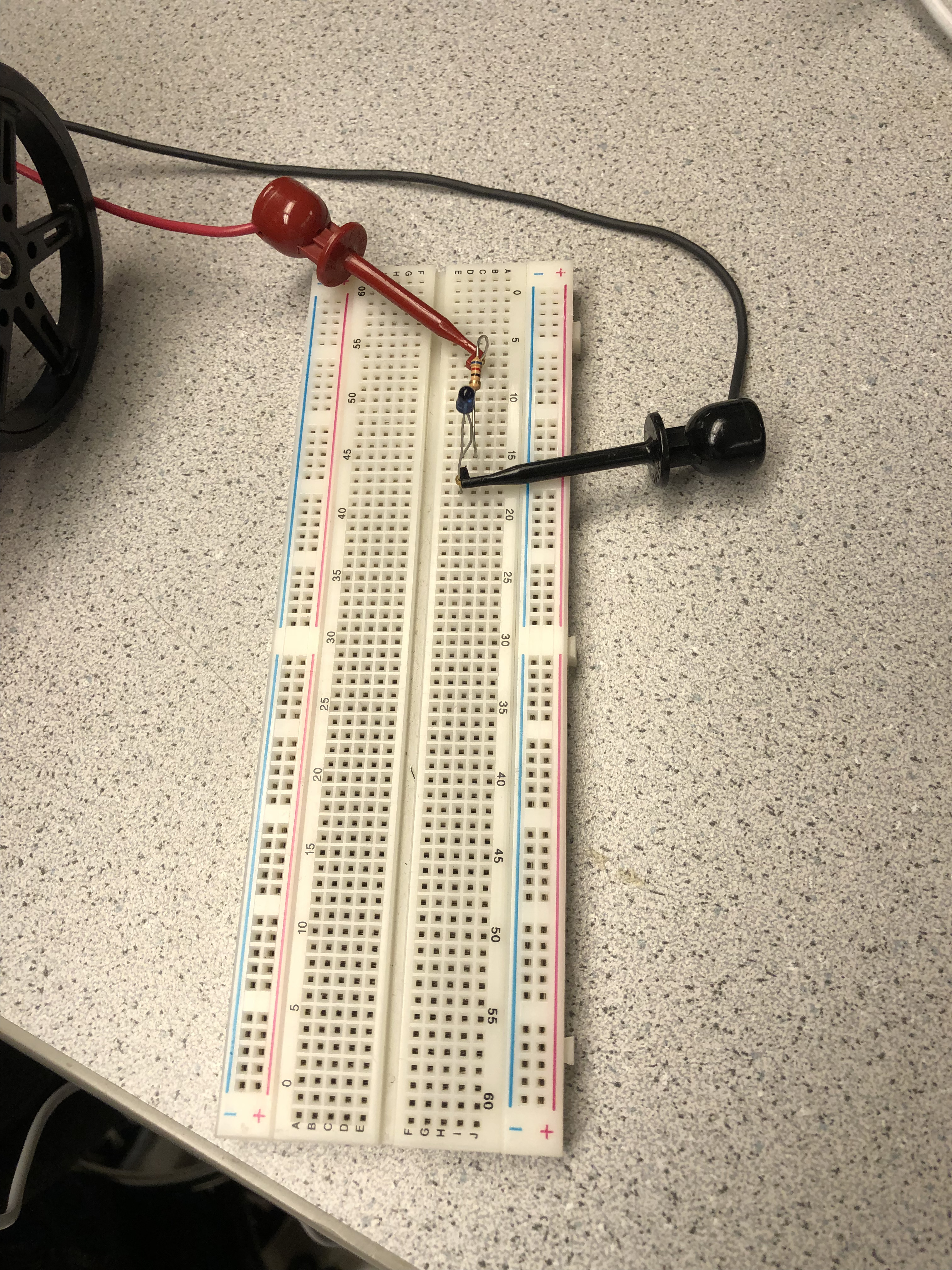
We also built an IR emitting circuit (on a separate breadboard) to emulate a treasure and used it to test the phototransistor circuit to ensure that BotMobile will be able to measure the IR signals from treasures.
& then connected the IR LED circuit to a signal generator that acted as a power source for the LED.
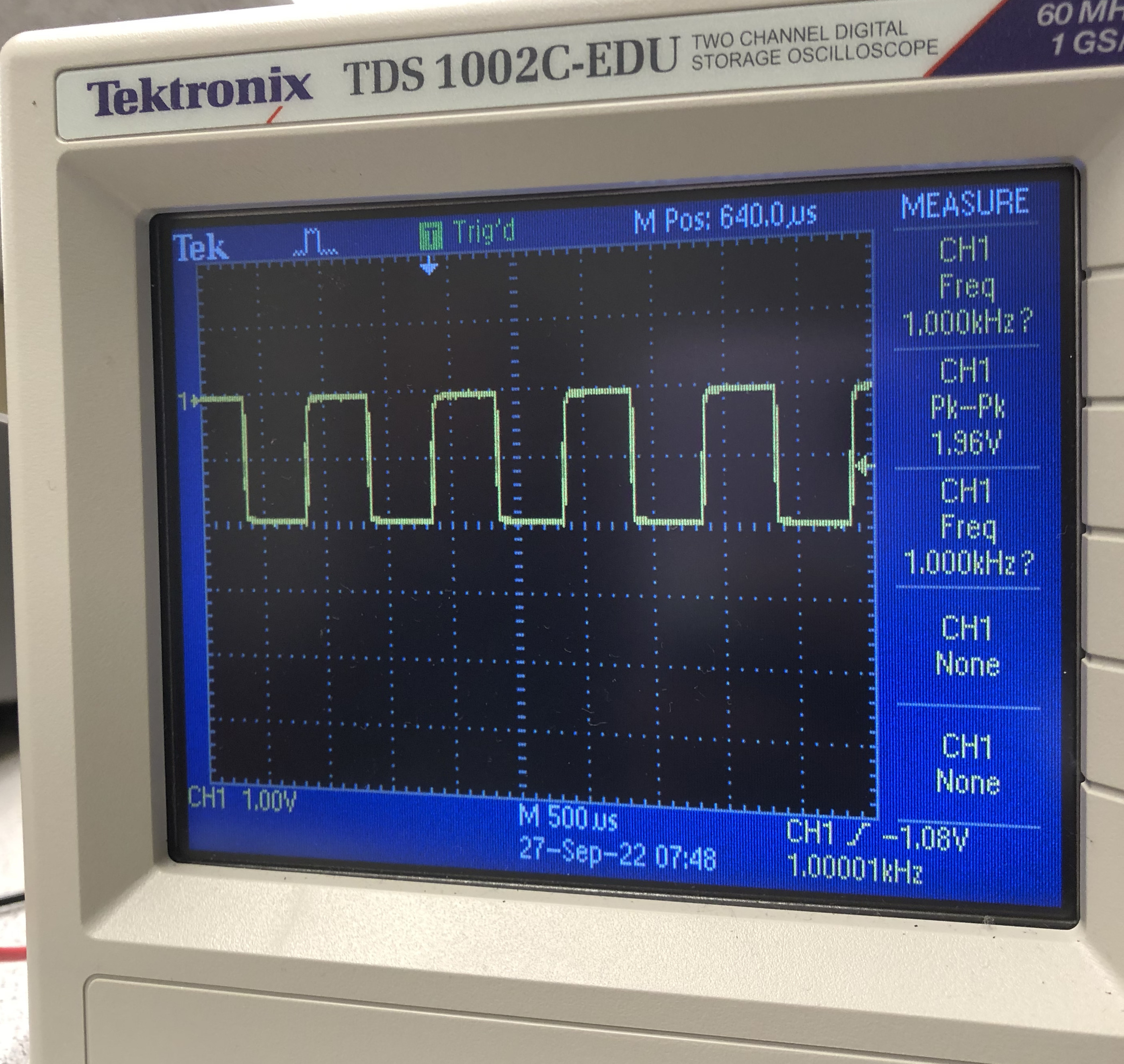
We used the oscilloscope to confirm that the signal generator is indeed generating a sinusoidal waveform with a the set frequency (1kHz) and a peak-to-peak voltage of 1.2V
- connecting the red wire of the oscilloscope’s BNC cable to were we connected the red wire from the signal generator & connecting the black wire from the oscilloscope to the black wire from the signal generator
Oscilloscope trace signal showing the trace for the 1kHz signal:
We then measured the signal that the phototransistor is transducing -> (1kHz then 9kHz from the IR LED)
- turning an optical signal into an electrical signal by connecting the red lead from the oscilloscope to the point of measurement of the phototransistor circuit
- moving around the LED to get an estimate of the rangeof voltage swing that your phototransistor measures from the blinking IR LED
Oscilloscope trace measurement of a 1kHz signal measured from the phototransistor on the main robot breadboard:
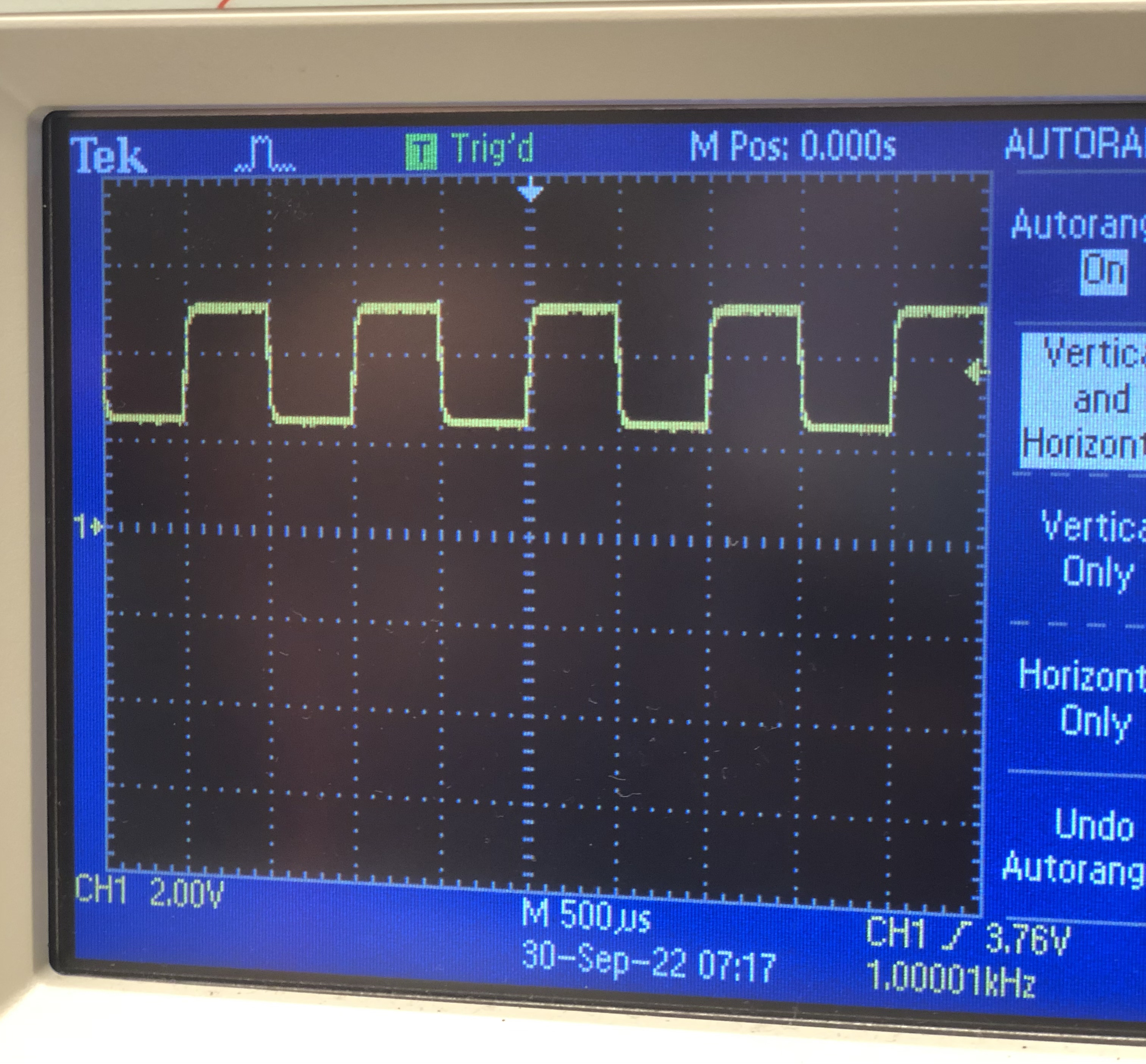
Oscilloscope trace measurement of a 1kHz signal measured from the phototransistor on the main robot breadboard:
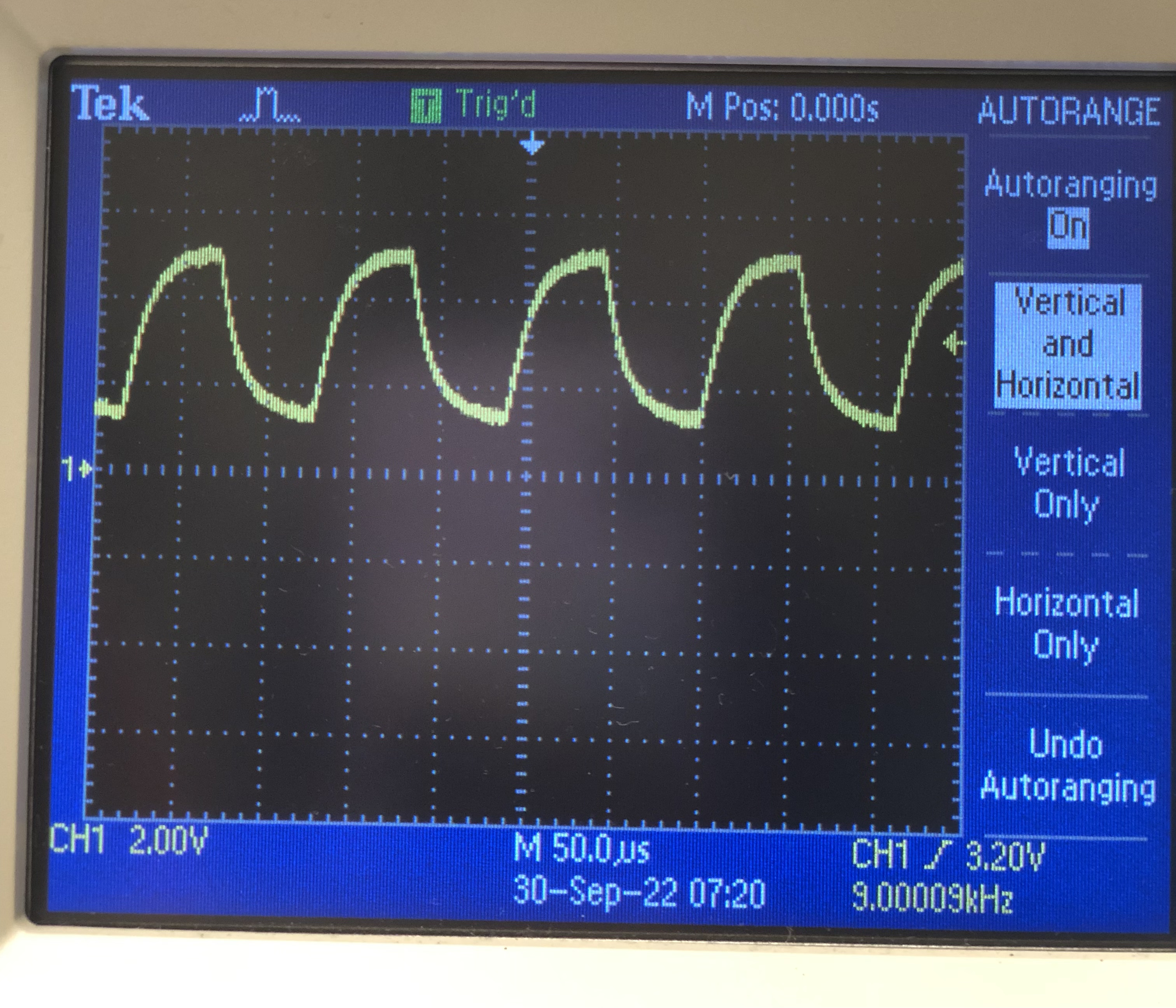
- The signal from the 9kHz signal appears distorted compared to the 1kHz signal because of the capacitance from the phototransistor, wires, oscilloscope make the signal take a while to charge and discharge (as detected by the phototransistor) causing it to be distorted
After confirming the functionality of the phototransistor circuit using the oscilloscope
- we used the Nano to measure the frequency -> connecting the output of the phototransistor circuit to an analog circuit on the Nano
- adjusted the Nano program to the room’s ambient light
- Read the signal frequency value from the Serial Monitor as seen below

Phase II
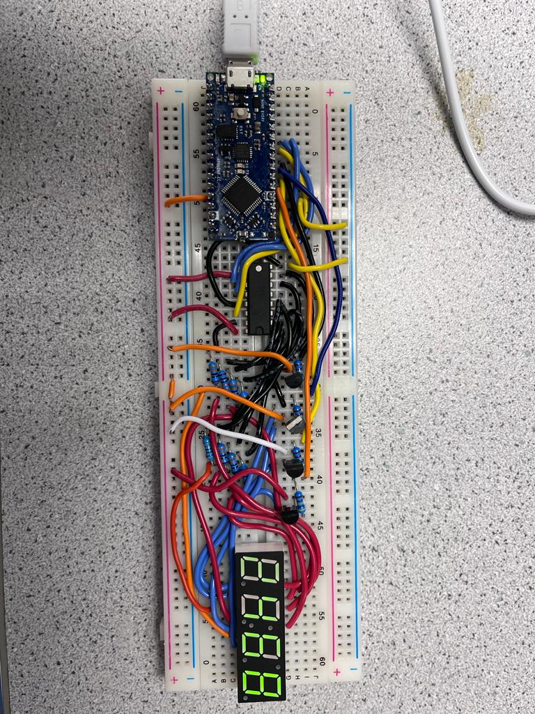
For the second phase of the lab, we built the display component of the base station on a separate breadboard, which we will later add Radio Frequency (RF) communication capability later on.
The base station consisted of a Nano, 4-digit 7-segment display, transisitors, and resistors
- transistors & resistors were used to protect the pins of the Nano that will be used to activate/power the 7-segment display
- also used a shift register to reduce the number of pins that will be used on the base station Nano
The image below shows the base station circuit displaying the number ‘2468’
Also modified the refresh period of the 7-segment display and observed the effect on the display for different periods (10s, 311s, 600s, 1000s)
10ms
- Display refresh rate not visible
311ms
- Display refresh rate barely visible
600ms
- Display refresh rate visible
1000ms
- Display refresh rate still visible and faster than the previous one
Next Steps: Adding an audio aspect to BotMobile