Lab 1 : Microcontrollers
Objective:
Develop an understanding of the function and purpose of microcontrollers by building and testing a simple autonomous robot. Using an Arduino Uno, control the motion of the robot by applying a PWM signal to a pair of Parallax servo motors through a program in the Arduino IDE. Learn how to assemble a well-structured robot and document progress in a Github repository.
Procedure:
The first part of the lab develops familiarity with the Arduino and Arduino IDE through a set of simple input/output tasks involving LEDs and potentiometers. The second part progresses to servo control and integration with the robot structure. We split into two groups to complete the first part and worked together on the second part.
Materials:
- 1 Arduino Uno
- 1 USB A/B cable
- 2 Continuous rotation servos
- 1 Pushbutton
- 1 LED
- 1 Potentiometer
- Several resistors (kΩ)
- 1 Solderless breadboard
Blinking LEDs:
We began with the “Blink” example sketch. In the Arduino IDE, we navigated to Files/Examples/01.Basic/Blink to find the code shown in "Code Snippet 1". After we compiled and loaded the sketch to the Arduino, the built-in LED on the Arduino began to toggle on and off as shown in the video 1 below.
	// the setup function runs once when you press reset or power the board
	void setup() {
	  // initialize digital pin LED_BUILTIN as an output.
	  pinMode(LED_BUILTIN, OUTPUT);
	}

	// the loop function runs over and over again forever
	void loop() {
	  digitalWrite(LED_BUILTIN, HIGH);   // turn the LED on (HIGH is the voltage level)
	  delay(1000);                       // wait for a second
	  digitalWrite(LED_BUILTIN, LOW);    // turn the LED off by making the voltage LOW
	  delay(1000);                       // wait for a second
	}
Code Snippet 1: Blinking Built-in LED
Video 1: Blinking Built-in LED
We then assembled a breadboard circuit with a red LED and 300-ohm resistor in series to protect our hardware, driven by the digital output from pin 13 on the Arduino. We modified the Blink sketch by setting pin 13 as a digital output instead of LED_BUILTIN as an output. We also sequentially set every digital pin as output to test all the pins.
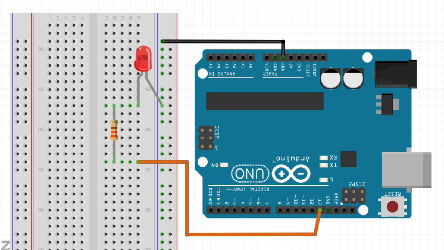
Schematic 1: Blinking External LED
	// the setup function runs once when you press reset or power the board
	void setup() {
	  // initialize digital pin 13 as an output.
	  pinMode(13, OUTPUT);
	}

	// the loop function runs over and over again forever
	void loop() {
	  digitalWrite(13, HIGH);   // turn the LED on (HIGH is the voltage level)
	  delay(500);               // wait for a second
	  digitalWrite(13, LOW);    // turn the LED off by making the voltage LOW
	  delay(500);               // wait for a second
	}
Code Snippet 2: Blinking External LED
Working with Analog Outputs and Potentiometers:
Using a potentiometer, we created a manually adjustable voltage divider. When a voltage divider was created with the 300Ω resistor, an analog pin was used to read the varying voltage. As you can see in Video 2, the potentiometer’s analog voltage changed as we adjusted the voltage divider.
int a0pin= A0;         // define analog pin being used
int val=0;             // initialize voltage value that will be outputted to screen

void setup() {
pinMode(a0pin, INPUT); // initialize analog pin 0 as an input
  Serial.begin(9600);  // Set baud rate for serial data transmission
}

void loop() {
  val= analogRead(a0pin); // Read in voltage from analog pin 0
  Serial.println(val);    // Print voltage value on the Serial monitor
  delay(500);
}
Code Snippet 3: Reading Analog Output from Potentiometer
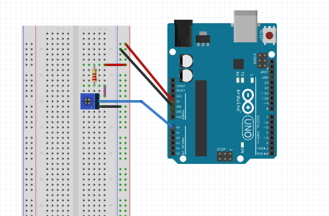
Schematic 2: Potentiometer Voltage Divider
Video 2: Potentiometer Voltage Divider Demo
Upon adding an LED to the circuit, we were able to control the brightness of the LED by controlling the voltage it received. To do this, the value of the potentiometer was taken using analogRead(pin), and mapped to a PWM output to create the effect of an analog output voltage on the digital pin, allowing the LED to change brightness.
int led = 9;    //Set pin 9 as LED
int a0= A0;     //Set analog 0 as potentiometer
int val=0;      //Initialize potentiometer voltage value
int dc=0;       //Initialize LED voltage value

void setup() {
  // Initialize LED, potentiometer, and serial connection
  pinMode(led, OUTPUT);
  pinMode(a0, INPUT);
  Serial.begin(9600);
}

void loop() {
  // Read voltage from potentiometer
  val= analogRead(a0);
  // Print potentiometer voltage
  Serial.println(val);
  // Map potentiometer voltage range to LED voltage range
  dc = map(val, 0, 1023, 0, 255);
  // Write voltage to LED
  analogWrite(9, dc);
}
Code Snippet 4: Potentiometer Changing Brightness of LED
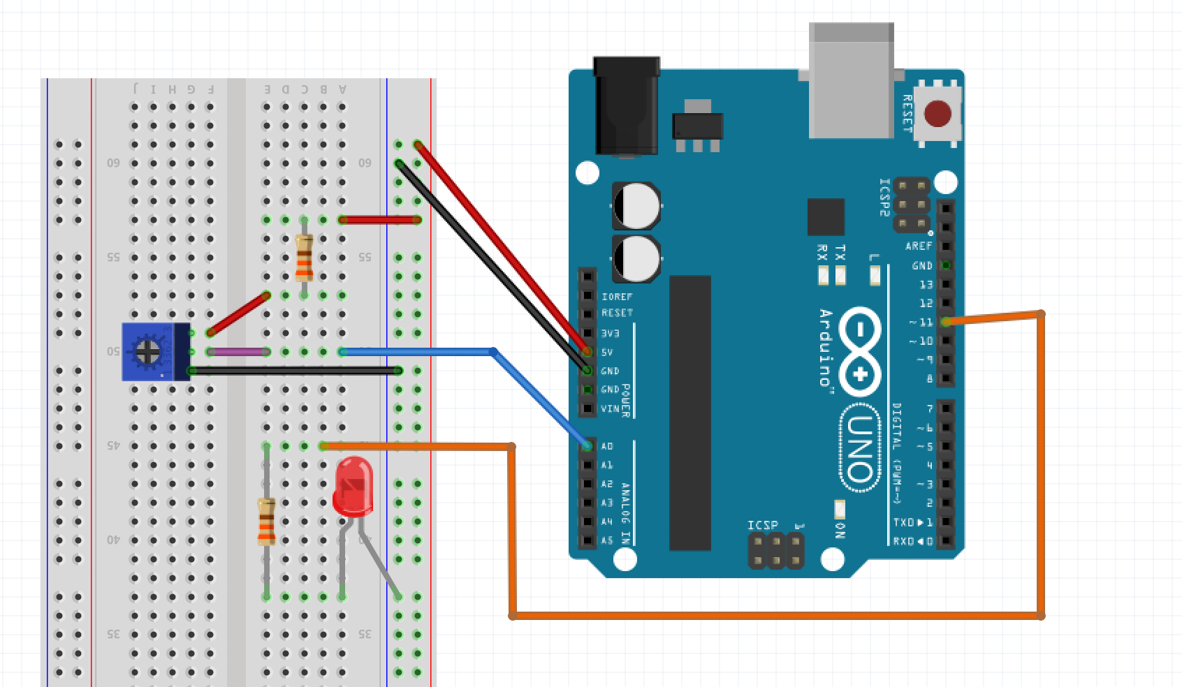
Schematic 3: Potentiometer and LED
Video 3: Potentiometer Changing Brightness of LED Demo
Parallax Servos:
In order for our robot to move, we used Parallax Continuous Rotation Servos. To set the servos up, we added the Servo library to our existing code and modified our mapping function to map the potentiometer’s analog voltage to the servo’s input range, from 0 (full speed one direction) to 90 (stopped) to 180 (full speed the opposite direction). This enabled us to change the speed and direction of the servo manually through the potentiometer.
#include
int a0= A0;    //Set analog 0 as potentiometer
int val=0;     //Initialize potentiometer voltage value
int dc=0;      //Initialize servo speed value
Servo servo;   //Initialize servo

//change servo speed by changing potentiometer output
void setup() {
  // Initialize servo, potentiometer, and serial connection
  servo.attach(9);
  pinMode(a0, INPUT);
  Serial.begin(9600);
}

void loop() {
  // Read voltage from potentiometer
  val= analogRead(a0);
  // Print potentiometer voltage
  Serial.println(val);
  // Map potentiometer voltage range to servo speed range
  dc = map(val, 0, 1023, 0, 180);
  // Write speed to servo
  servo.write(dc);
}
Code Snippet 5: Potentiometer Controlling Servo
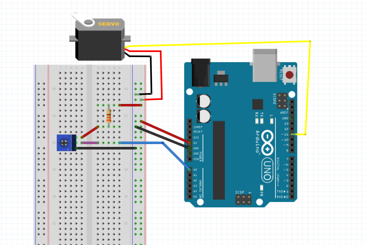
Schematic 4: Potentiometer and Servo
Video 4: Potentiometer Changing Speed and Direction of Servo Demo
Robot Assembly:
We constructed our robot by attaching one Parallax servo to both the left and right sides of our chassis using 3D printed motor mounts. Wheels that meshed well with the splines on the output shafts of the servos were attached using a screw for each wheel. The ball bearing was attached to the rear of the frame using a standoff to extend the height of the assembly. A second chassis plate was mounted above the main chassis using the tall 3D printed brackets to allow a mounting point for the Arduino. A breadboard was placed on top of the lower chassis and the battery was mounted to the bottom of the frame between the servos using velcro. Figure 1 shows a top view of our robot and Figure 2 is a side view. Figure 2 includes other updates that we added to the robot in Milestone one such as traction for wheels and line sensors.

Figure 1: Top View of Robot
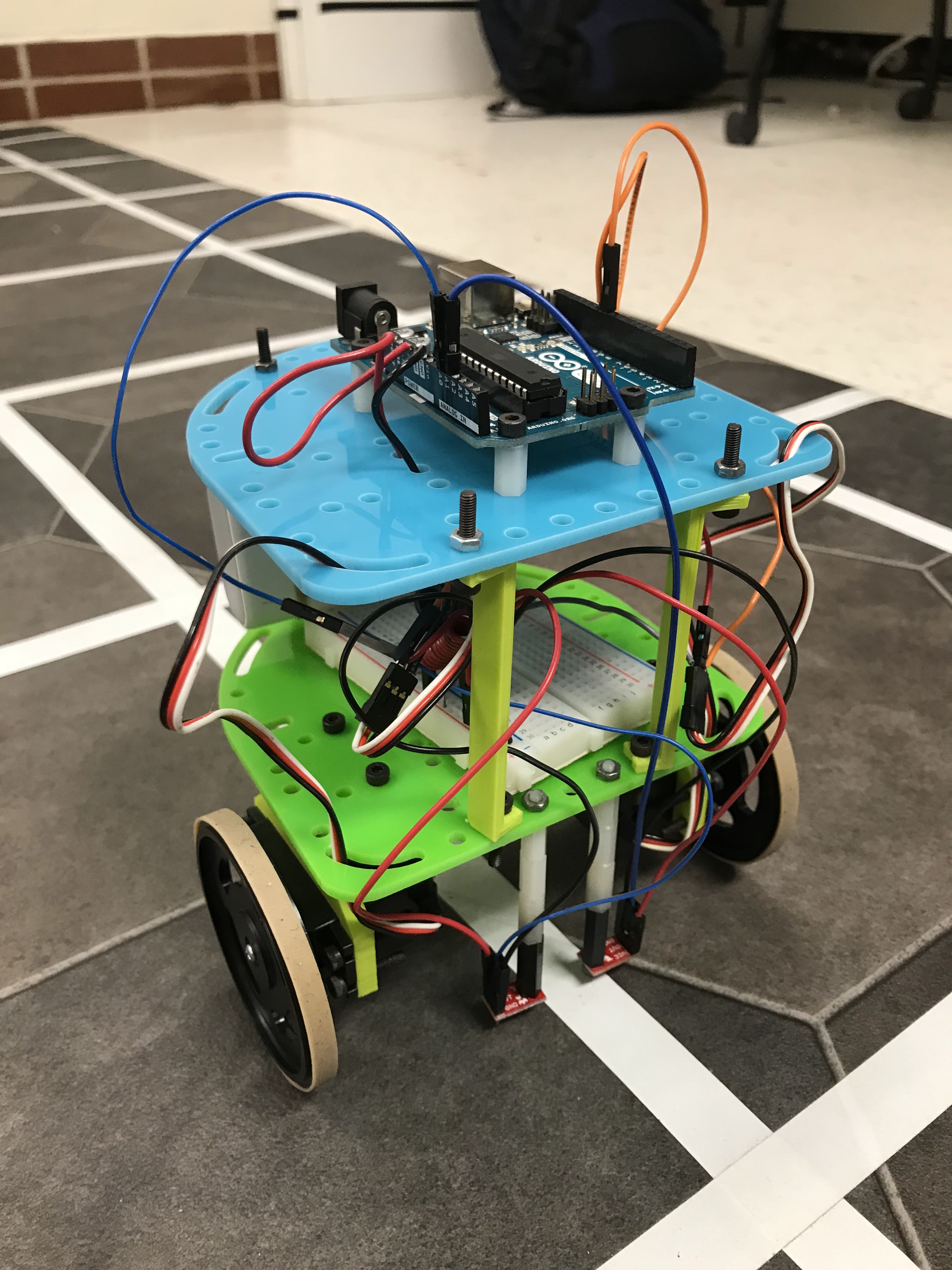
Figure 2: Side View of Robot
Driving the Robot Autonomously:
Once we assembled the robot, we programmed it to autonomously drive in a square by repeatedly moving forwards at full speed for a second then turning left 90 degrees as seen in Video 5 and Code Snippet 6.
#include

// Initialize right and left servo
Servo rServo;
Servo lServo;

void setup() {
  // Attach servos: right to 10 and left to 11
  rServo.attach(10);
  lServo.attach(11);
}

void loop() {
  // continually drive forward then turn right, making a square
  goForward();
  turnLeft();
}

// goForward() drive forward for one second
void goForward() {
  rServo.write(0);
  lServo.write(180);
  delay(1000);
}

// turnLeft() turn left 90 degrees
void turnLeft() {
  rServo.write(0);
  lServo.write(0);
  delay(700);
}
Code Snippet 6: Autonomous Driving
Video 5: Autonomous Driving Demo