Milestone 1
Objective:
Use IR line sensors to program the robot to follow a straight line and follow a figure eight path mapped out on a grid.
Hardware Assembly:
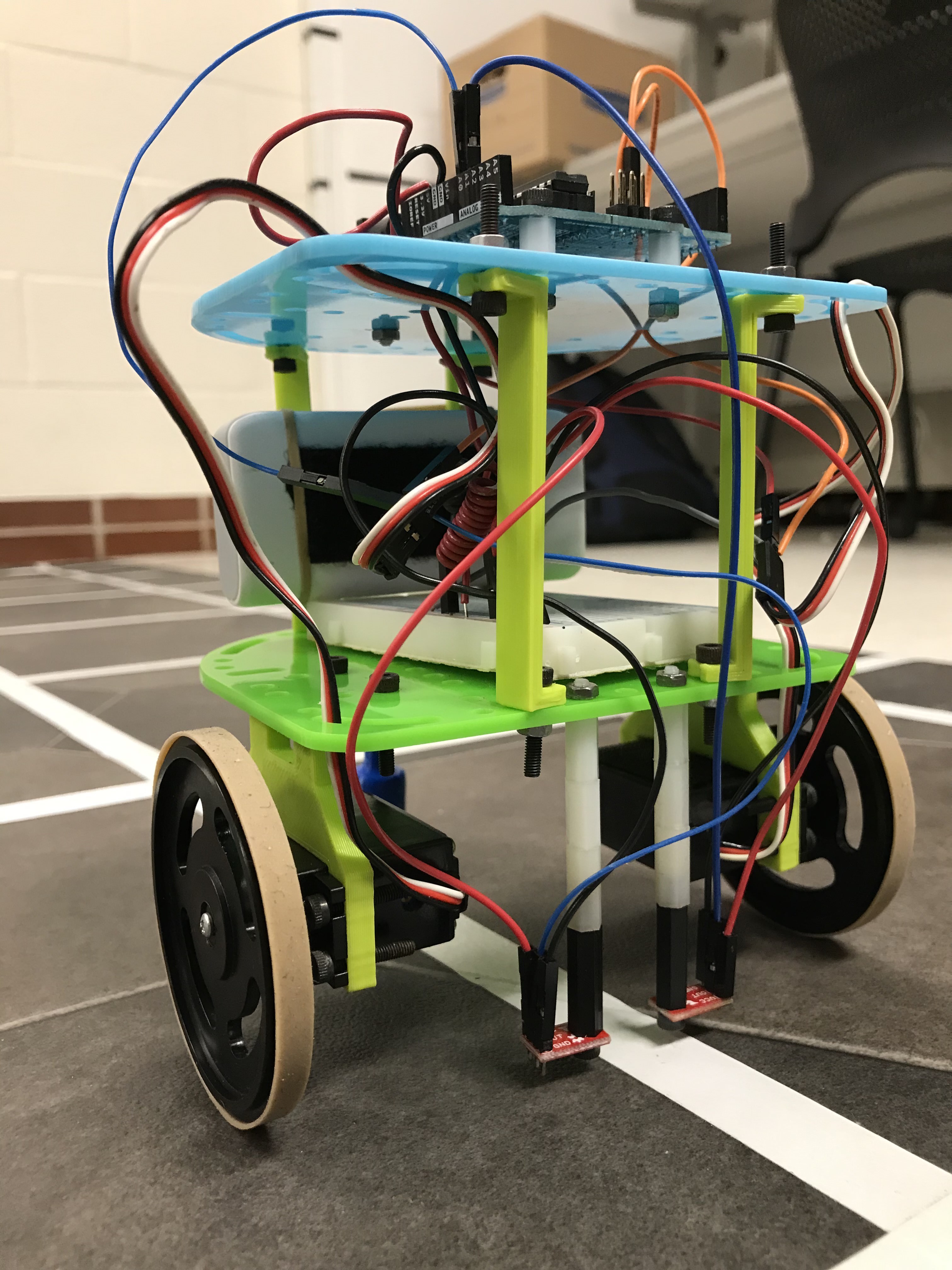
We modified the robot by adding two IR line sensors centered on the front of our robot, separated by a distance slightly wider than that of the white lines on the competition field. The sensors were each mounted on a series of connected standoffs to hold the sensors a couple millimeters above the ground. The sensor configuration can be seenin Figure 1 below. We decided on using two sensors because this is the minimum number of sensors to accurately follow along the line while remaining centered and we did not want to complicate the design any more than we need to. With this sensor arrangement, the robot follows the line with one sensor on each side, and if either sensor begins to sense the white line, the robot will correct itself to straighten out until both sensors again sense the dark background.

Figure 1: IR Line Sensors on Robot
In order to get our robot to follow a line, we had to calibrate the line sensors and find a threshold value. This threshold value we calculated was 750. We arrived at this threshold by calculating the average value between the value that the line sensor detected when on the black mat and the value that the line sensor detected when on the white line. This threshold value was then used so that the robot could use the 2 line sensors to determine whether it was veering off the line towards the left, veering off the line towards the right, or maintaining a straight path.
While we were setting up the line sensors, we had the option to either set the line sensors as analog inputs or digital inputs. After reading through the bildr website for line sensing (https://bildr.org/2011/06/qre1113-arduino/), we decided to go with the analog option. Going down the analog path resulted in more concise code since the analog version just outputs an analog voltage on the signal pin. This voltage indicates how much light was reflected back. The digital version is more complicated, requires a lot more code, and is really only designed for scenarios in which you no longer have any unused analog pins on your arduino.
Line Following:
When deciding the configuration of our sensors, we also took into account whether it would be feasible or effective to implement line-following functionality. Given that we deemed our new assembly method worthy at the beginning of the lab period, the final implementation ended up being rather close to what we envisioned and can be seen in Video 1 below.
Video 1: Line Following Robot
Since the sensors are spaced slightly wider than the line, one of three readings are possible:
- Both sensors read dark (greater than our threshold)
- The right sensor reads dark (> threshold) and the left reads light (< threshold)
- The right sensor reads light (< threshold) and the left reads dark (> threshold)
In terms of programming this, our setup() function entails setting the pins correctly and ensuring the robot is not moving. Our loop() function simply calls a function called linefollow() that abstractly works as follows:
- Get a reading from the sensors
- If the robot is in state 1 described above, simply go straight full speed ahead
- If the robot is in state 2, veer left
- If the robot is in state 3, veer right
For states 2 and 3, we had to play with the speeds of the different motors. We did not want to stop the motor nearer to the line entirely because the motion of the robot would not be as smooth. Instead, we slowed down the motor closer to the white enough such that the robot would stay on course. If we did not slow the motor enough, the robot would lose track of the line. The slowing of the motors was significant, but because it is not a full stop then the zigzag motion of the robot is much smoother that is we stopped one side entirely. We tested this just by observing the motion of the robot using different adjustments and deciding on one that resulted in the most satisfactory balance of a sharp turn and a smooth path.
Based on observations made here and in lab 1, the speed of the motor does not seem to be linearly proportional to the value passed to Servo.write(). Rather, the speed decreases sharply as the values approach 90 from either direction. We ended up using a value just 5 away from 90 (95 for left, 85 for the right). All of the programming logic discussed in this section can be seen in Code Snippet 1 below.
#include <Servo.h>

// Initialize right and left servo
Servo rServo;
Servo lServo;

// Assign right line sensor to A0 and left line sensor to A1
int rLineS = A0;
int lLineS = A1;

// Initialize line sensor values
int rLineV;
int lLineV;

// Initialize line sensor threshold to 750
int thresh = 750;

void setup() {
  // Attach servos: right to 10 and left to 11
  rServo.attach(10);
  lServo.attach(11);
  // Initialize line sensors
  pinMode(rLineS, INPUT);
  pinMode(lLineS, INPUT);
  // Begin serial connection
  Serial.begin(9600);
  // Stop the robot for a second before beginning
  stopMoving();
  delay(1000);
}

void loop() {
  // continually follow lines
  lineFollow();
}

// Makes the robot follow a straight line, ignoring intersections
void lineFollow() {
  readLine();

  if(rLineV > thresh && lLineV > thresh){
    goForward();
  }
  else if (rLineV > thresh && lLineV <= thresh){
    corrLeft();
  }
  else if (rLineV <= thresh && lLineV > thresh){
    corrRight();
  }
  else {
    goForward();
  }
}

// Makes the robot stop
void stopMoving() {
  rServo.write(90);
  lServo.write(90);
}

// Collects data from both line sensors
void readLine() {
  rLineV = analogRead(rLineS);
  lLineV = analogRead(lLineS);
}

// Drives robot forward at full speed
void goForward() {
  rServo.write(0);
  lServo.write(180);
}

// Slows down the left wheel so the robot veers left
void corrLeft() {
  rServo.write(0);
  lServo.write(95);
}

// Slows down the right wheel so the robot veers right
void corrRight() {
  rServo.write(85);
  lServo.write(180);
}
Code Snippet 1: Line Following
Figure Eight:
The placement of our IR line sensors is wide enough such that when following a straight line, either none of the sensors is over the white line or at most one is over the white line. These conditions correspond to the states that govern line tracking: straight ahead, correct left, or correct right. Conveniently, the robot is in neither of these states when it crosses an intersection because both sensors will momentarily detect the intersecting line. Indeed, this fact helps us uniquely define our third basic state, which is crossing an intersection.
Once the robot detects that it has reached an intersection, it must execute a 90-degree turn and center its sensors over the new line. If the robot begins turning immediately when both sensors detect the intersecting line, the feedback from the sensors will likely be erratic and unexpected during the turn because there is no way to detect the transition from the current line to the intersecting line. To more rigorously define the pattern that we expect to see from the line sensors, we allow the robot to move past the intersecting line until the wheels align with the intersection and then initiate the turn. For example, if the robot turns right, we know the right sensor has to cross the new white line first, followed by the left sensor.
Even after moving the sensors past the intersection a small amount, the robot still exhibited some unpredictable behaviors. In particular, it would usually initiate the turn but then stop after turning a small angle. We realized that the initial state of the turn was undefined, since our line-following algorithm can only guarantee that overall the robot stays on track, not that the robot will always stay perfectly centered on the white line. We found that the turn was failing because the robot was sensing the end condition of the turn before it had even left the line it was tracking, rather than when it detects the intersecting line.
To fix this, we decided to rely less on the sensors and more on the time. We hard-coded the wheels to turn for 750 ms, which then gave the sensors a better chance of detecting the end condition. So, after the wheels started to turn, the sensors waited 750 ms. Then they read the data from the sensors until the wheel on the outside of the turn read a value greater than the set threshold value (detecting the white line), and then the robot was programmed to stop. The time delay for the sensors to turn on again was decided through trial and error. Using a delay of more than 750 ms caused the robot to overshoot the turn.
Video 2: Figure 8 Robot
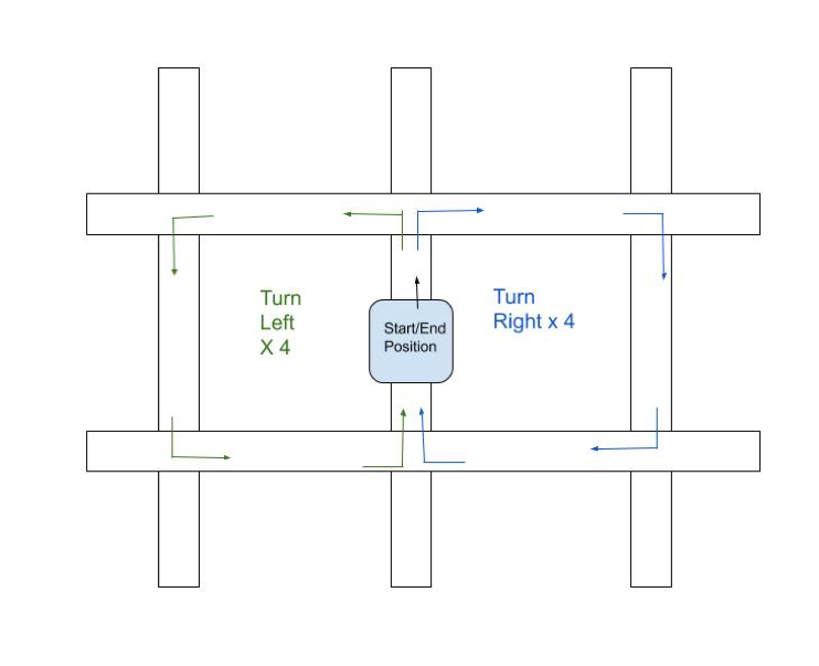
Once we were able to program a 90° left and right turn using the sensors, we implemented a figure 8 turn which can be seen in Video 2 above. To do this, we had a series of conditions to implement line following corrections while having the robot repeat 4 left turns followed by 4 right turns as seen in Figure 2 below.

Figure 2: Figure 8 Pattern
The pattern was created by using a counter that would reset after completing all 8 turns. This created a repeating figure 8 pattern for the robot to complete. All of the programming logic discussed in this section can be seen implemented in Code Snippet 2 below.
#include <Servo.h>

// Initialize right and left servo
Servo rServo;
Servo lServo;

// Assign right line sensor to A0 and left line sensor to A1
int rLineS = A0;
int lLineS = A1;


// Initialize line sensor values
int rLineV;
int lLineV;

// Initialize turn counter to 0
int cnt = 0;

// Initialize line sensor threshold to 750
int thresh = 750;

void setup() {
  // Attach servos: right to 10 and left to 11
  rServo.attach(10);
  lServo.attach(11);
  // Initialize line sensors
  pinMode(rLineS, INPUT);
  pinMode(lLineS, INPUT);
  // Begin serial connection
  Serial.begin(9600);
  // Stop the robot for a second before beginning
  stopMoving();
  delay(1000);
}

void loop() {
  // continually follow lines in figure eight shape
  lineFollow();
}

// Makes the robot follow lines, deciding which direction to turn at intersections
void lineFollow() {
  readLine();

  if(rLineV > thresh && lLineV > thresh){
    goForward();
  }
  else if (rLineV > thresh && lLineV <= thresh){
    corrLeft();
  }
  else if (rLineV <= thresh && lLineV > thresh){
    corrRight();
  }
  else {
    turn();
  }
}

// Makes the robot stop
void stopMoving() {
  rServo.write(90);
  lServo.write(90);
}

// Collects data from both line sensors
void readLine() {
  rLineV = analogRead(rLineS);
  lLineV = analogRead(lLineS);
}

// Drives robot forward at full speed
void goForward() {
  rServo.write(0);
  lServo.write(180);
}

// Slows down the left wheel so the robot veers left
void corrLeft() {
  rServo.write(0);
  lServo.write(95);
}

// Slows down the right wheel so the robot veers right
void corrRight() {
  rServo.write(85);
  lServo.write(180);
}

// Turns robot left at an intersection
void turnLeft() {
  goForward();
  delay(200);
  stopMoving();
  rServo.write(0);
  lServo.write(0);
  delay(750);
  while(rLineV > thresh) {
    readLine();
  }
  stopMoving();
}

// Turns robot right at an intersection
void turnRight() {
  goForward();
  delay(200);
  stopMoving();
  rServo.write(180);
  lServo.write(180);
  delay(750);
  while(lLineV > thresh) {
    readLine();
  }
  stopMoving();
}

// Turns robot left at 4 consecutive intersections, then turns robot right at next 4
//intersections, repeats
void turn() {
  if (cnt < 4) {
    turnLeft();
  }
  else {
    turnRight();
  }
  cnt = (cnt + 1) % 8;
}