Milestone 3
Objective:
- Have the robot successfully avoid other robots (at least 1ft distance)
- Demonstrate that the robot is capable of maze exploration using DFS, BFS, Dijkstra, or A* (show that your robot can do different maze configurations, one of them to be a minimum size of 4' X 5')
Robot Detection:
When we first started implementing robot detection, we built a simple circuit for the IR detector and IR emitters (940 nm wavelength) with pull-up resistors and without any amplification just so we could see what the arduino was able to detect. We wired the output of the IR detector as an analog input on the arduino and printed the values being sent to the arduino on the serial monitor. The behavior we observed was that as the emitter moved closer to the detector, the value printed on the serial monitor started to decrease. While we were able to see that the detection was working, the emitter and detector had to be very close to each other and aligned perfectly to work properly. In order to remedy this, we decided to use a BJT amplifier for the detector.
Using the ElectronicWings guide for IR communication, we were able to properly amplify the photodiode’s signal with different resistance values. The strongest signal we got was by using a 120K Ω resistor on the anode of the photodiode, which enabled IR LED detection from around a foot away.
After constructing the BJT amplifier, we also decided to switch from using an analog input to a digital input. The output of the amplifier would feed into a digital pin on the arduino and we wrote a small function to recognize robots which would be incorporated into our code for line following and wall detection.
void readIR(){
  IRval = digitalRead(IRpin);
  if(IRval==1){
    turnAround();
 }
Robot Detection Code Snippet
This change significantly helped increase the distance that the detection would work from and increased the width of the detection cone (wider angle). After adding the BJT circuit and switching from analog to digital, the IR detector was able to sense the emitter from more than a foot away.
The video below shows that the IR detector located on the breadboard that is on the lab bench is able to sense the IR emitter that we are moving up and down. The green LED lights up to indicate that detection is ocurring.
IR Emitter Detection Video
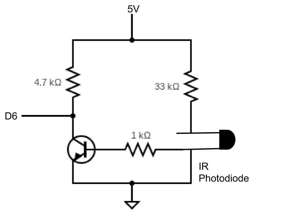
Once we were able to see that the detection mechanism was working, we attached the sensor and emitters to our robot. We attached the sensor to the front of the robot and attached an emitter to each side, all of which were 5 inches above the ground. But upon testing this circuit on the robot in the maze, the robot was detecting itself from the reflection of its own IR LED off of the wood. So, we damped the signal by swapping the 120K Ω resistor with a 33K Ω resistor, which was still able to detect robots, but with a less intense signal. The schematic for the final amplifier can be seen below.

IR Detection Circuit
The first video below show that the robot is able to detect the IR emitter on its own. The second video shows that it can perform wall sensing and robot detection together.
Robot Detection Video
Robot Detection and Wall Sensing Video
Maze Exploration:
The maze can be represented as a grid formed by the intersections of the white lines, with walls as obstacles that limit the number of possible directions the robot can turn at any given intersection. The robot must visit every point on the grid that is accessible to it (i.e. not completely walled off on four sides). Therefore, the navigation algorithm must not only traverse every accessible grid location but be intelligent enough to recognize when it has finished mapping the maze, including the possibility that it will never reach a completely closed-off area.
While the wall-following algorithm implemented in Milestone 2 performs well when the maze is fully-connected (i.e. there are no wall segments which are unconnected to the rest of the maze), it cannot be guaranteed to traverse all accessible grid points if the maze is not fully connected or if there are large open areas. However, if we think of the maze as a collection of explorable nodes connected by openings in the walls, we can use a tree data structure to represent the maze. This approach immediately opens itself up to the two main tree-traversal algorithms, depth-first search (DFS) and breadth-first search (BFS). Our group decided to implement DFS rather than BFS because, unlike in software, it takes our robot a significant amount of time to make turns and return to a visited node. While DFS only returns to a visited node after it has fully explored all possible child nodes, BFS returns to the parent node every time it finds a child node, which is too costly for our robot. We decided against shortest-path algorithms like Djikstra’s and A* because the goal is not to find a “goal” node using the shortest path in a known graph, but rather to fully traverse and map an unknown graph.
We implement the DFS algorithm using a recursive structure, with the DFS function calling itself every time the robot visits a new child node. When the robot runs out of valid, unvisited child nodes, it will return to the parent node. If we imagine the maze as a tree, the robot will go from the root node all the way to the first leaf node, and then return and explore the next leaf node, and the next, until the entire tree has been visited. To keep track of the grid, we create a two-dimensional boolean array with the same size as the grid whose values are whether or not the node at the corresponding coordinates have been visited. We use this structure not only to determine where to direct the robot, but also to determine when we have finished mapping the maze.
We keep track of the robot’s orientation (represented using the cardinal directions) and its x- and y-coordinates as global state variables in the code. When the robot arrives at a new intersection, it first polls the wall sensor data to determine whether there are walls on its left, right, or front directions. It also checks whether the adjacent nodes corresponding to those directions have or have not yet been visited using the boolean grid array. If the node exists and it has not yet been visited, the robot will proceed to visit the node and recursively call DFS. We prioritize visiting the node in front, if it exists, since going forward through an intersection is less costly than making a turn. When the robot returns to a parent node and all the possible child nodes have been visited, it will then return to the parent’s parent. We do this by storing the successive parent coordinates on the function call stack, which automatically pops the “grandparent” location when we return to a parent node. In this way, the robot backtracks until it either finds a parent node that still has unvisited child nodes or it has completed the maze traversal.
The general implementation of the algorithm described above can be seen in the code snippet below.
void DFS(int x_par, int y_par) {
  grid[y][x] = true;
  int x_curr = x;
  int y_curr = y;

  Serial.print(x);
  Serial.print(y);
  Serial.println();
  // Child search sequence
  bool existsChild = true;
  while (existsChild) {
    readWall();
    if (fWallV < fw_thresh_0 && !checkForward()) {
      Serial.println("forward");
      keepForward();
      lineFollow();

      DFS(x_curr,y_curr);
    }
    else if (lWallV < sw_thresh_0 && !checkLeft()) {
      Serial.println("left");
      turnLeft();
      lineFollow();

      DFS(x_curr,y_curr);
    }
    else if (rWallV < sw_thresh_0 && !checkRight()) {
      Serial.println("right");
      turnRight();
      lineFollow();

      DFS(x_curr,y_curr);
    }
    else {
      existsChild = false;
    }
  }

  // backtrack
  Serial.println("return");
  if (x_par == x && y_par < y) {  // parent to the north
    switch(dir) {
      case 0: keepForward(); lineFollow(); break;
      case 1: turnLeft(); lineFollow(); break;
      case 2: turnAround(); lineFollow(); break;
      case 3: turnRight(); lineFollow(); break;
      default: stopMoving(); Serial.println("stop");
    }
  }
  else if (x_par > x && y_par == y) { // E
    switch(dir) {
      case 0: turnRight(); lineFollow(); break;
      case 1: keepForward(); lineFollow(); break;
      case 2: turnLeft(); lineFollow(); break;
      case 3: turnAround(); lineFollow(); break;
      default: stopMoving(); Serial.println("stop");
    }
  }
  else if (x_par == x && y_par > y) { // S
    switch(dir) {
      case 0: turnAround(); lineFollow(); break;
      case 1: turnRight(); lineFollow(); break;
      case 2: keepForward(); lineFollow(); break;
      case 3: turnLeft(); lineFollow(); break;
      default: stopMoving(); Serial.println("stop");
    }
  }
  else if (x_par < x && y_par == y) { // W
    switch(dir) {
      case 0: turnLeft(); lineFollow(); break;
      case 1: turnAround(); lineFollow(); break;
      case 2: turnRight(); lineFollow(); break;
      case 3: keepForward(); lineFollow(); break;
      default: stopMoving(); Serial.println("stop");
    }
  }
  return;
}
DFS Code Snippet
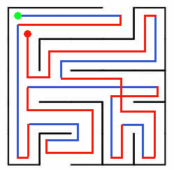
Here is a simple maze that illustrates the DFS algorithm. The blue lines indicate exploring new child nodes, while the red lines indicate backtracking.

DFS Algorithm Illustration
Here are videos of our robot completing a 3x3 maze and a 5x5 maze.
3x3 Maze Mapping Video
5x5 Maze Mapping Video