Milestone 2 Right Hand Wall Following
Objectives
For milestone 2, we want the robot to successfully circle an arbitrary set of walls while following the line. For now, we use the right-hand wall following rule. So the robot will always follow the wall on its right.
- Materials Used:
- 1 Arduino Uno
- 1 USB A/B Cable
- 2 IR Sensors
- Variuos Resistors
- LM358 Op-Amp
- 1 Solderless breadboard
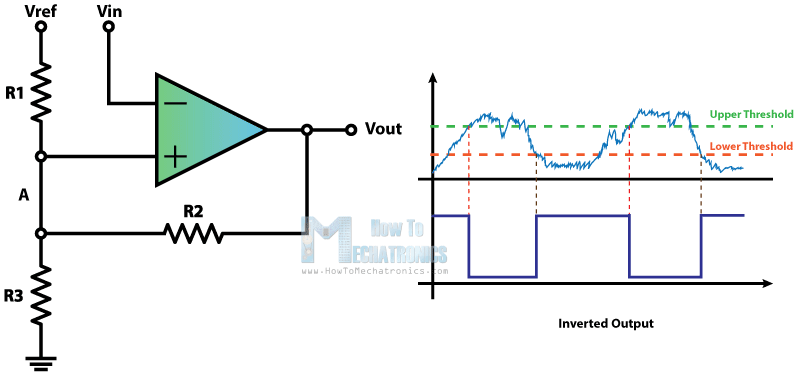
1. We began this session by verifying that our robot’s Schmitt triggers were working. An image of the schematics of the Schmitt Trigger circuit we are using is shown below. For detailed information on the Schmitt trigger, see Lab 2. We also refined our robot’s turning so that it stayed on the line. In the past, it had cut corners. We changed the code to have the robot move slightly past each intersection before making a sharp 90-degree turn. This was essential for wall following and future movement in the maze because the robot would have run into walls if it did not stay on the line for every stage of its turns.

2. In order to start the wall following, we mounted two wall sensors to the robot. To do this, we added a second chassis to create a second level to the robot. We mounted wall sensors to the right side and front of the robot, which we needed to do right-hand wall following. We began by soldering the wall sensors onto wires that could easily be integrated into our existing Arduino and breadboard. In order to get a sense of how the wall sensors worked, we held them at different distances from the wooden walls. This allowed us to get a sense of the range of the IR sensors and the values that were read at different distances. We converted the analog values into float decimals and decided a threshold value for both the right and front wall sensors. This value decided when the robot had come close enough to a wall and had to make a decision.
3. The robot was then coded to do a right-hand search around a set of walls. This involved keeping the robot on the grid and turning right whenever there was no longer a wall there. If there was a wall, the robot would go forward. If both the right and front sensors detected walls, the robot turned left. This basic sequence of statements allowed the robot to traverse on the right side of a set of walls. At this point, the Arduino was reading values from the two line sensors and the two wall sensors and making logical decisions in real-time. The video is shown here.
4. Then we start to make the robot follow a line. To follow a line, we arranged the line sensors to be on either side of the line. This involves sensing when both sensors are above black sections. If either sensor is on the white line, the robot will readjust itself so that the sensors will again straddle the white line. This worked well, and our robot followed the line. It was even able to readjust itself when it started to go off course. The video below shows the robot following a straight line.
5. Lastly, we added a green LED to show what the robot was “thinking.” we added an LED digital output to our Arduino that would light up whenever the robot saw a wall. We will build on this in the future as we will need to discern between seeing walls and seeing robots. The video below shows the LED circuit that we built in lab. The green LED will only light up when the robot detects a wall on its right.