Lab 1 (Microcontrollers)
During this lab, we worked on becoming familiar with the Arduino board and its functions. We also built the robot and worked towards Milestone 1, achieving line sensing capability and traversal of the grid in a figure eight pattern.
Basis of Code and Circuitry for Robot Development
Step 1: Blinking an internal LED
The first step in this lab was to use the example sketch in the Arduino IDE to make the internal LED on the board blink slowly. Below is the code and a video of the demonstration.
Code
// the setup function runs once when you press reset or power the board
void setup() {
  // initialize digital pin LED_BUILTIN as an output.
  pinMode(LED_BUILTIN, OUTPUT);
}

// the loop function runs over and over again forever
void loop() {
  digitalWrite(LED_BUILTIN, HIGH);   // turn the LED on (HIGH is the voltage level)
  delay(1000);                       // wait for a second
  digitalWrite(LED_BUILTIN, LOW);    // turn the LED off by making the voltage LOW
  delay(1000);                       // wait for a second
}
Step 2: Blinking an external LED
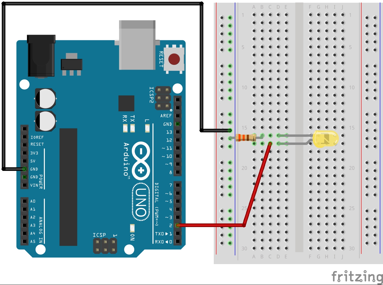
The next step was to test each of the digital pins and we did this by writing a loop that would toggle all the pins to be tested high or low each second. The test implemented an external LED that would turn on when the pin's signal was high and off when the signal was low. This way, we loaded code only once and only had to move the jumper wire connecting the pin to the LED's anode in order to verify the function of the pin.
Code
#define DIGITAL_13 13
#define DIGITAL_12 12
#define DIGITAL_11 11
#define DIGITAL_10 10
#define DIGITAL_9  9
#define DIGITAL_8  8
#define DIGITAL_7  7
#define DIGITAL_6  6
#define DIGITAL_5  5
#define DIGITAL_4  4
#define DIGITAL_3  3
#define DIGITAL_2  2
#define DIGITAL_1  1
#define DIGITAL_0  0

// the setup function runs once when you press reset or power the board
void setup() {
  Serial.begin(9600);
  Serial.print("LED_BUILTIN = ");
  Serial.println(LED_BUILTIN);

  // initialize all digital pins as an output.
  pinMode(DIGITAL_13, OUTPUT);
  pinMode(DIGITAL_12, OUTPUT);
  pinMode(DIGITAL_11, OUTPUT);
  pinMode(DIGITAL_10, OUTPUT);
  pinMode(DIGITAL_9, OUTPUT);
  pinMode(DIGITAL_8, OUTPUT);
  pinMode(DIGITAL_7, OUTPUT);
  pinMode(DIGITAL_6, OUTPUT);
  pinMode(DIGITAL_5, OUTPUT);
  pinMode(DIGITAL_4, OUTPUT);
  pinMode(DIGITAL_3, OUTPUT);
  pinMode(DIGITAL_2, OUTPUT);
}

// the loop function runs over and over again forever
void loop() {
  for (int i = DIGITAL_2; i <= DIGITAL_13; i++)
  {
    digitalWrite(i, HIGH);          // turn the LED on (HIGH is the voltage level)
  }
  delay(1000);                      // wait for a second
  for (int i = DIGITAL_2; i <= DIGITAL_13; i++)
  {
    digitalWrite(i, LOW);           // turn the LED off by making the voltage LOW
  }
  delay(1000);                      // wait for a second
}
Circuit Schematic

Step 3: Reading voltage values from a potentiometer
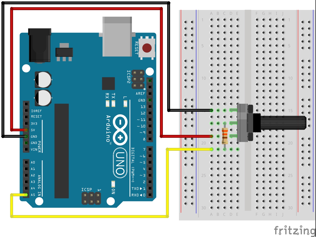
Following the digital pin test, we tested the functionality of the analog pins. These pins are able to read analog voltage signals, and we used a potentiometer to test if the pins' readings would change as the potentiometer's resistance was varied. A potentiometer is a variable resistor that acts as a voltage divider in a circuit. Since analog pins that were not wired would print floating values, we only printed the output of the pin being tested and uploaded modified code when changing the pin. The code below shows the test for pin A5
Code
#define ANALOG_5      A5

unsigned long time_ref;
unsigned long time_comp;

// the setup function runs once when you press reset or power the board
void setup() {
  Serial.begin(9600);

  time_ref = millis();
  time_comp = millis();
}

// the loop function runs over and over again forever
void loop() {
  time_ref = millis();

  if (time_ref - time_comp >= 500)
  {
    time_comp = millis();;
    Serial.print(analogRead(ANALOG_5));
  }
}
Circuit Schematic

Step 4: Varying the brightness of an LED with a potentiometer
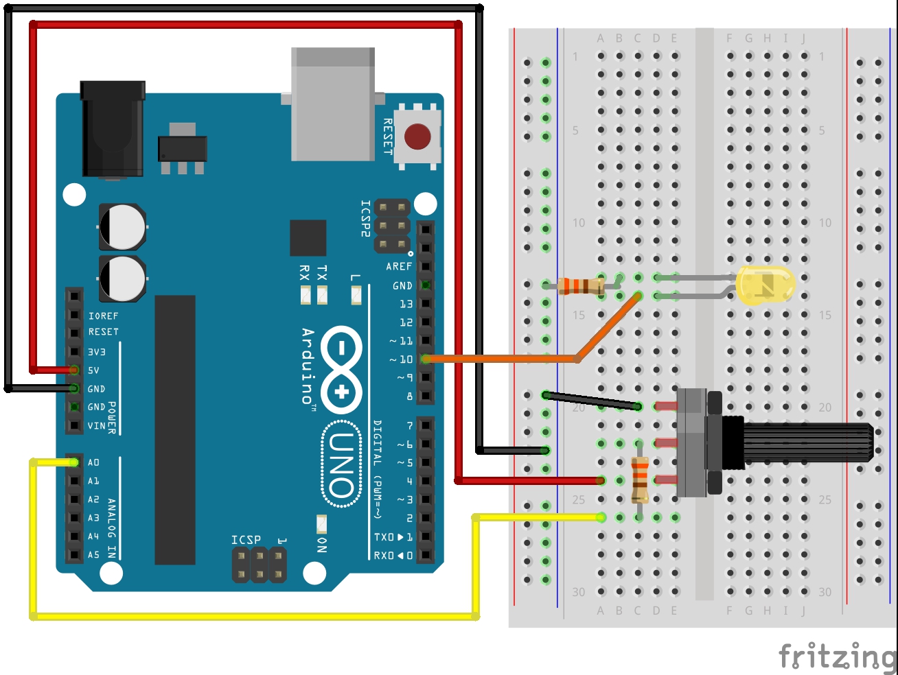
We then used the code from the analog read and the external LED steps to create code that allowed the brightness of the LED to be changed through the rotation of the potentiometer's knob. This code implemented pulse width modulation (PWM), which allows the modification of a digital signal's duty cycle to have the effect of changing an analog signal's voltage level.
Code
// pin definitions
#define POT_PIN       A0
#define LED_PIN       10

void setup() {
  Serial.begin(9600);

  // set digital pins as outputs
  pinMode(LED_PIN, OUTPUT);
}

void loop() {

  // read analog value from the potentiometer, in [0, 1023]
  int pot_value = analogRead(POT_PIN);

  // print this value so we know our value is actually changing
  Serial.println(pot_value);

  // re-scale value to be within the values [0, 255]
  int led_value = map(pot_value, 0, 1023, 0, 255);

  // write the new value to the LED
  analogWrite(LED_PIN, led_value);
}
Circuit Schematic

Step 5: Controlling a servo with a potentiometer
This step is very similar to Step 4 for controlling the LED, but there is an additional Servo object added in the code. This Servo object has a write() method that allows a number from 0 to 180 to be written to control both the speed and orientation of its rotation. This method allows for a proper scaling of the PWM duty cycle for the servo, as the standard 0 to 255 scaling for LED's would not work. In this step, the servo motor is wired to 5V from the Arduino board, and the output pin is connected to the signal channel of the servo.
Below is the code we used for this step. There are two Servo variables defined, but only one is demonstrated in the example video.
Code
#include// pin definitions #define LED_PIN 8 #define SERVO1_PIN 5 #define SERVO2_PIN 6 #define POT_PIN A5 // private definitions Servo servo1; Servo servo2; void setup() { Serial.begin(9600); servo1.attach(SERVO1_PIN); servo2.attach(SERVO2_PIN); pinMode(POT_PIN, INPUT); } void loop() { int pot_value = analogRead(POT_PIN); int servo_value = map(pot_value, 0, 1023, 0, 180); Serial.println(servo_value); servo1.write(servo_value); }
Circuit Schematic

Below is a video demonstrating the operation of one servo in both clockwise and counter-clockwise directions
Assembly and Autonomous Control of the Robot
Robot Assembly
There were a variety of resources provided to us to assemble the robot. The list below outlines the main components in our robot as of the completion of this lab.
- Chassis
- 2 Servo Motor Mounts
- 2 Rubber Wheels
- 3 Line Sensors
- Line Sensor Mounts
- Ball Bearing Attachment
- Breadboard
- Arduino
- USB Cable
- Rechargeable Battery with USB port
- 1 red LED
- 1 green LED
- 2 potentiometers
- 330Ω Resistors
- Nuts, Bolts, Jumper Wires
To construct the robot, we started with the base plate and servo mounts. We positioned the servos such that the wheels directly attached to the servos would tip the robot slightly forward. The robot maintains its balance with the addition of a third leg, a ball bearing that acts as a caster. After putting the chassis together, we mounted our line sensors in the front, along the edge where the ball bearing is screwed on. We decided to go with a 3 sensor design, one in the middle to track the white tape, and two on either side of the tape tracking the darker background to detect drift and intersections. Finally, we added external battery mounting posts.
After putting the hardware together, we wired the sensors and servos to a breadboard, then connected the breadboard to the corresponding pins and power on the arduino. Wiring management is currently by colored jumper wire, but we plan on soldering perf board once the design is finalized.