Lab 1 - Microcontrollers
Objective
The goal of this introductory lab was to become more familiar with the functionalities of the Arduino Uno and the Arduino IDE by using LEDs, potentiometers, and parallax servos. Once we became more comfortable, we put together a robot and had it perform a simple task.
Materials Used
- 1 Arduino Uno
- 1 USB A/B Cable
- 1 Continuous Rotation Servo
- 1 LEDs
- 1 Potentiometer
- Resistors
- 1 Solderless breadboard
- 1 Chassis
- 2 Wheels
- Assorted screws
- Ball bearings
Procedure
Blinking LEDs
To begin the lab, we opened up the blink sketch and examined it to understand how it works. We successfully blinked the internal LED with the following code:
        void setup() {
          pinMode(LED_BUILTIN, OUTPUT);  //This initializes the LED_BUILTIN as an output
        }

        void loop() {
          digitalWrite(LED_BUILTIN, HIGH);  //Turns the LED on
          delay(1000);  //Leaves the LED on for one second
          digitalWrite(LED_BUILTIN, LOW);  //Turns the LED off
          delay(1000);  //Leaves the LED off for one second
        }
Next, we replaced the internal LED (LED_BUILTIN) with an external LED. We did this by connecting the output of a digital pin to an LED. A resistor was added in series to prevent the LED from burning out.
        void setup() {
          pinMode(5, OUTPUT);  //This uses pin 5 as an output for the external LED
        }

        void loop() {
          digitalWrite(5, HIGH);  //Turns the LED on
          delay(1000);  //Leaves the LED on for one second
          digitalWrite(L5, LOW);  //Turns the LED off
          delay(1000);  //Leaves the LED off for one second
        }
Analog Read & Write with Potentiometer
Connecting the Potentiometer
We then took advantage of 'analogRead' function to output analog voltage values being controlled by the potentiometer. .
        int sensorPin = A0;
        int voltageValue = 0;

        void setup() {
          Serial.begin(9600);
        }

        void loop() {
          voltageValue = analogRead(sensorPin);
          Serial.println(voltageValue);
          delay(1000);
        }
To write analog PWM voltages to the external LED, we used the `analogWrite` function
        int sensorPin = A0;
        int LEDPin = 6;
        int voltageValue = 0;

        void setup() {
          pinMode(sensorPin, INPUT);
          Serial.begin(9600);
          pinMode(LEDPin, OUTPUT);
        }

        void loop() {
          voltageValue = analogRead(sensorPin)/5.7;
          Serial.println(voltageValue);
          delay(1000);
          analogWrite(LEDPin, voltagevalue);
        }
We then replaced the LED with a servo, which is a type of motor that spins with controllable speed and position. This involved including the Servo.h library using #include. This allows us to use the preexisting library for the Servo. Unlike a traditional servo that outputs position values between 0 and 180, the parallax servo assigns different rotational speeds and directions. For example, a value of 90 will stop the servo while the ranges 91-180 and 0-89 correspond to different speeds in opposite directions.
        #include <Servo.h>

        //create servo object, output/input pins
        Servo myservo;
        int pwnPin = 6;
        int analogPin = A0;
        int val = 0;

        void setup() {
          Serial.begin(9600);
          myservo.attach(pwnPin);    //connected to pwm digital pin output
        }

        void loop() {
          delay(1000);
          val = analogRead(analogPin) / 1024 * 180;   //map analog input range to servo output range
          myservo.write(val);      //servo's speed and direction determined by analog voltage read
        }
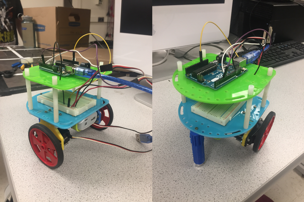
Assembling & Testing the Robot
Next, we assembled our robot using a chassis, two wheels along with their mounts, a ball bearing, and an arduino. Using the servo control we learned in the previous step, we set up the servo motion such that both wheels ran in opposite directions.
        void moveforward() {
          left.write(180);
          right.write(0);
        }
Performing an Autonomous Task