Lab 2 - FFT
Objective
In lab 2, we designed analog circuitry and used Fast-Fourier Transform to determine whether a 950 Hz tone had be played..
Materials Used
- 1 Arduino Uno
- 1 USB A/B Cable
- Resistors
- Capacitors
- 1 Microphone
- A lot of wires
Procedure
Analog Circuitry
We first started by putting together the simple microphone circuit together and testing for a working microphone by connecting the output to an oscilloscope and detecting an output when we tap on the microphone. Once we found a working microphone, we decided to solder wires to the microphone so that we have more flexibility with where we place the microphone.
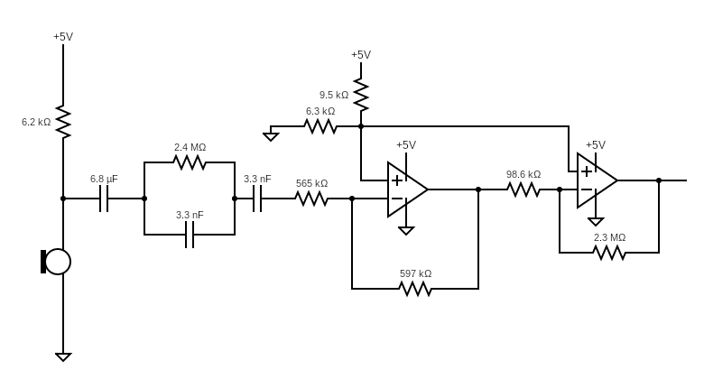
In order to process the proper output from the microphone, we amplify the output ofthe microphone. To do this, we first implemented a simple inverting amplifier. We decided to use the LM358 op amp package, along with resistors with high resistancevalues since it operates at a low current. The gain for a single stage can be described as –(R2/R1), and we need a gain of at least 100 in order to have the output of the microphone show up such that we can detect the 950Hz frequency correctly. In order to do so, we decided to cascade two op amp stages together, withthe first stage having a gain of around 15 and the second stage having a gain of around 25, giving an overall gain of around 375.
We also have to avoid cutting off at the maximum value of the op amp, which will be tied to the 5V line of the Arduino, so we set up a simple voltage divider in order to have a DC offset to the signal in both op amps. Initially we had the voltage divider send in a 2.5V offset by having two equal-valued resistors, but after experimentation, we found that having a lower voltage at the offset allowed the output to be amplified more before being cut off.
When testing the output of the microphone circuit with the amplifier circuit, we saw a significant amount of noise that we wanted to filter out. In order to reduce the noise, we implemented a series RC and a parallel RC impedance at the input in order to filter out the more extreme values and avoid amplifying part of the noise. The series RC component of the input filter has an impedance given as Z = R + (1/jwC) which will filter out lower frequency values since |Z| increases with lower frequencies, while the parallel RC component has an impedance of Z = (R/1 + jwRC)which will filter out the higher frequency values. Having implemented this, we ended up with the following circuit:
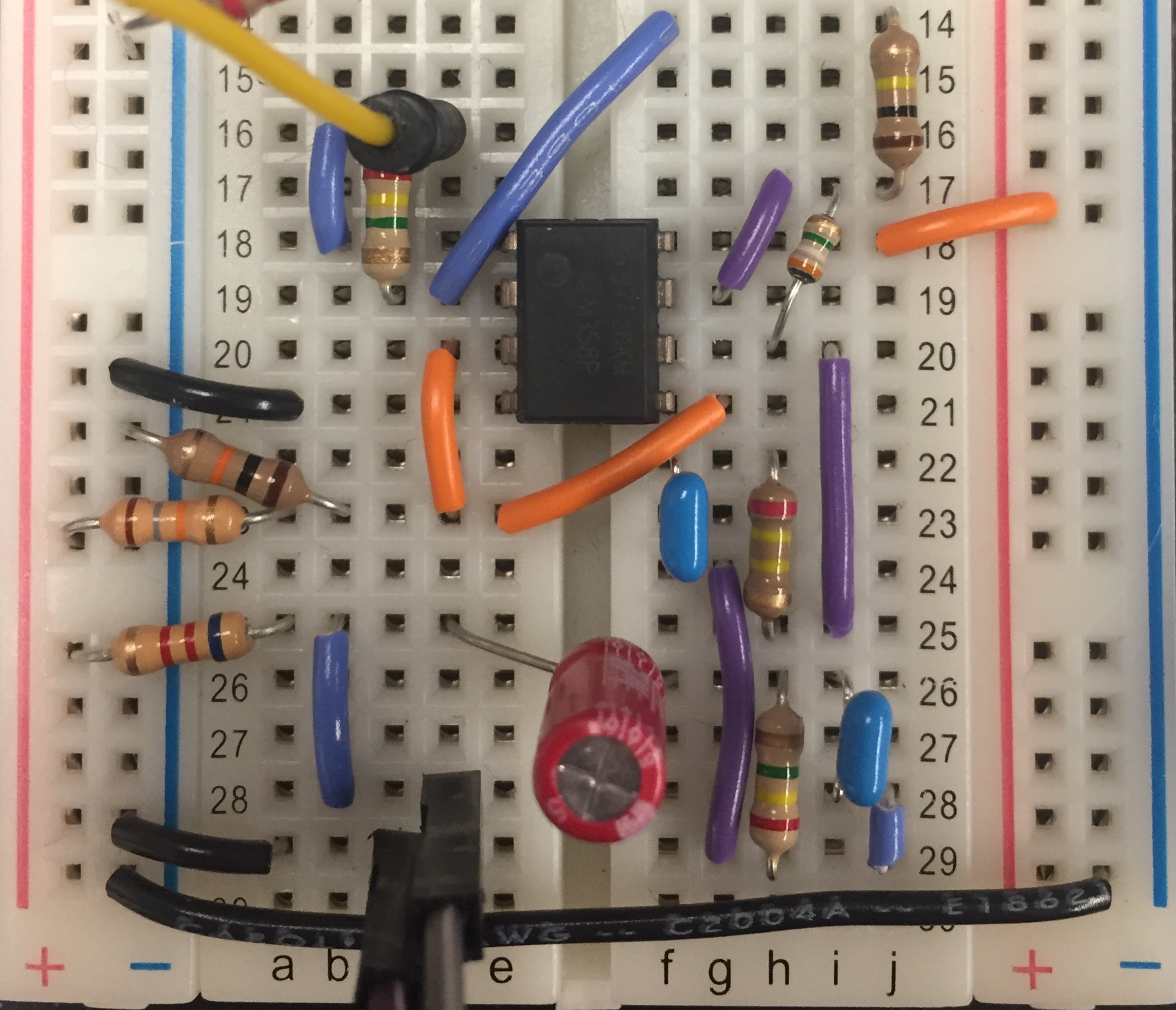
This is our circuit on the breadboard.
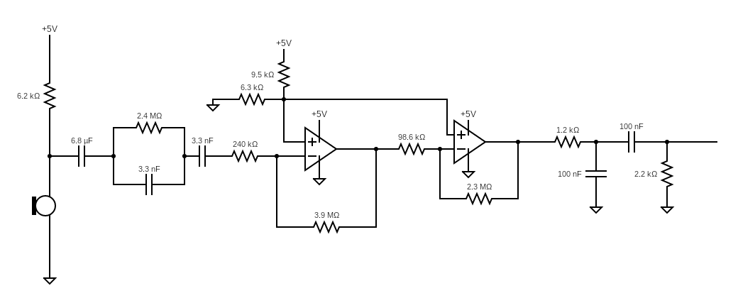
For the additional circuit, we decided to include an additional output filter on the amplifier circuit, as there was still some unwanted noise in the output. More specifically, we decided to implement a passive band pass filter made to have a central frequency closer to the 950Hz frequency we wanted to detect. The band pass filter involves a low pass and a high pass section; the first half is the low pass filter which blocks out high frequencies, while the second half is the high pass filter which blocks out low frequencies. The central frequency is determined by the square root of the product of the cut off frequencies for each of the two filters, and each cut off frequency is determined by the formula f = (1/2(pi)RC). Using these formulas, we decided to hold the capacitor values constant at 100nF and pick out the closest resistor values that give the desired central frequency. Combining it with the original circuit, we end up with the following circuit and filtered output:
Fast Fourier Transform
Fourier Transform breaks a signal into an alternate representation characterized by sine and cosines and shows that any waveform can be re-written as the sum of sinusoidal functions. It is used to map signals in the time domain into its constituent frequencies in the frequency domain. In a signal’s frequency representation, we can observe a signal's spectrum and analyze the magnitude of various frequencies to see which frequencies are more present than others.
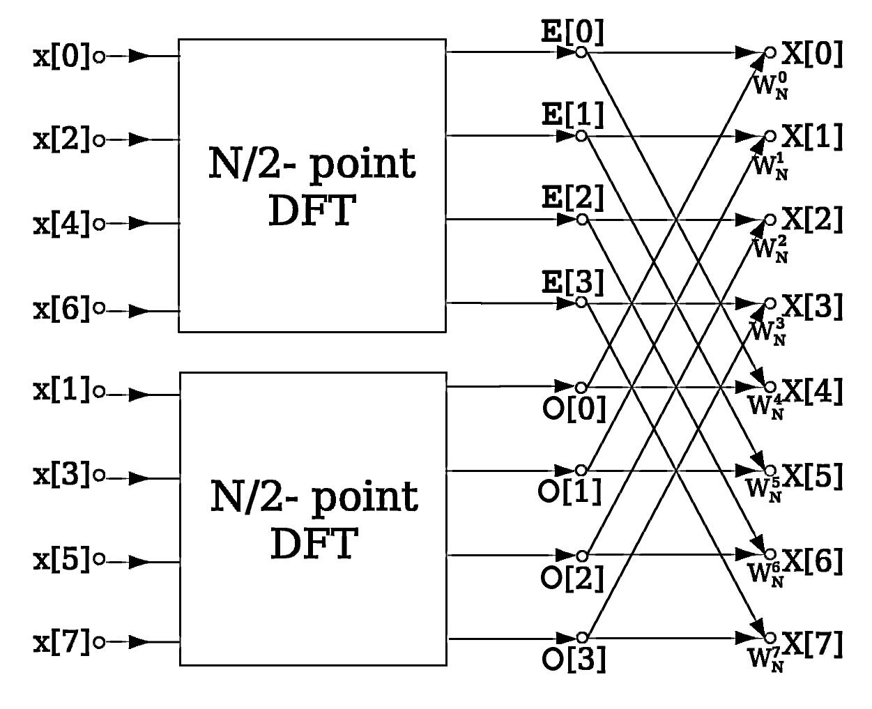
The standard way to do this is to use Discrete Fourier Transform. However, we want to speed this process up, so we use a Fast Fourier Transform, which is a divide and conquer algorithm where you divide the signal into two smaller signals, compute the DFT of the two smaller signals and join them to get the DFT of the larger signal.
The FFT algorithm was implemented using Open Music Labs Arduino FFT Library that was provided to us. The example code from the ibrary takes in an analog signal from Arduino pin A0, samples it at 256 equally spaced intervals, and returns an array with 128 values, which represent the magnitude of the frequency content for frequenices up to half of the samping frequency. Since the FFT of a real signal is symmetric over zero, only half of the outputs are unique, and thus 128 bins are returned.
When we monitored the Serial output of the bins with its corresponding magnitude when a 950 Hz tone was played, we realized that we needed to look at bin 6 and monitor the surrounding bins as well.
      #define TARGETBIN 6
      #define THRESHOLD 150
      ...

      void loop() {
        while(1) { // reduces jitter
          ...
        }
        ...

        if ( (fft_log_out[TARGETBIN-1] >= THRESHOLD-30) && (fft_log_out[TARGETBIN] >= THRESHOLD) && (fft_log_out[TARGETBIN+1] >= THRESHOLD )){
          Serial.println("yuh this works");
        }
      }