Lab 3 - FPGA Video Controller
Objective
In lab 3, we created a video controller with an FPGA, controlled by an Arduino. To do this, we developed a system to transfer information from the Arduino to the FPGA and learned how to interact wih the video memory and the VGA driver.
Materials Used
- 1 DE0-Nano Development Board
- Arduino Uno
- Resistors
- DAC Circuit board
- VGA cable
- A lot of wires
Procedure
FPGA
For the FPGA, our goal was to use a DE0-Nano to process the maze traversal information from the Arduino. In order to do that, we first set up communication between the FPGA board and the VGA display. To do so, we downloaded the template file and followed the lab instructions (found here) to set up the clocks for each of the componenets provided. Then, there are a few things that had to be changed:
- The screen width and screen length were changed to 264 by 264 such that the drawing is not too small
- The IMAGE PROCESSOR module needs to output the X_ADDR, Y_ADDR, and W_EN values for the memory module to use, and we do not need the input VGA_PIXEL_X and VGA_PIXEL_Y, so we changed the inputs/outputs accordingly.
- In order to store enough locations in memory for the increased screen width and length that we want to draw, the memory addresses all had to be changed from 15 bits to 18 bits in length.
After the changes above, we had to figure out how we wanted to draw the maze. We do this in IMAGE_PROCESSOR.v and it takes in an 11 bit value. The 4 most significant bits represent the X position in the maze, the next 4 bits represent the Y position in the maze, and the last 3 bits represent the outputs of the wall sensors (left, front, and right walls). While working through the required logic for this, we ended up with three important always blocks that all work at the rising edge of the clock. These blocks are responsible for figuring out the orientation of the robot in the maze, detecting a new input, and drawing out the walls, respectively.
In order to keep track of the way the robot is facing, a dedicated always block was created for this. To do so, we track the previous X and Y locations that were sent by the Arduino and decide using the present and previous locations to figure out which way the robot is facing. This assumes that we only receive information from the Arduino when it reaches a new intersection.
      always @ (posedge CLK) begin
        if (init == 2'd3) begin
          if (X_PREV < X)           ORIENTATION = East;
          else if (X_PREV > X)      ORIENTATION = West;
          else if (Y_PREV > Y)      ORIENTATION = South;
          else if (Y_PREV < Y)      ORIENTATION = North;
          else                      ORIENTATION = ORIENTATION;
        X_PREV = X;
        Y_PREV = Y;
        end
      end
The second always block is responsible for detecting a new input from the Arduino. We have to include this block in order to know when we should restart the process of drawing the walls and in Verilog we are unable to control an update flag inside two separate always blocks. To compensate, we use this block to control an update flag that indicates for one cycle that there is a new value from the Arduino. In response, the wall drawing block we will discuss next resets all the counters to 0 for that cycle.
      always @ (posedge CLK) begin
        if (PIXEL_PREV != PIXEL_IN) update = 1'b1;
        else update = 1'b0;
        PIXEL_PREV = PIXEL_IN;
      end
The last always block is responsible for drawing out the walls in the corresponding locations. We decided to draw the maze by using walls that are 4 pixels wide and paths in between walls that are 22 pixels wide. Inside this block, we utilize two counters for each of the walls that we want to draw: the first one is responsible for drawing the length of the wall, which comes out to 30 pixels, and the second one is responsible for drawing the width of the wall, which is 4 pixels. We draw a wall that is 30 pixels in length in order for the walls to connect properly. Once the update flag is set to low after a new value is passed in, we check whether there are walls detected by each of the wall sensors. If there are no walls detected by a given sensor, then we set the value of the corresponding counters for the wall to their maximum value. If all of the counters are at their maximum value, we set the W_EN value to low and arbitrarily set the output color and positions to 0.
      always @ (posedge CLK) begin
        if (update) begin
          left = 5'd0;
          left_aux = 2'd0;
          front = 5'd0;
          front_aux = 2'd0;
          right = 5'd0;
          right_aux = 2'd0;
          W_EN = 1'b0;
          RESULT = 8'b0;
          X_ADDR = 18'd0;
          Y_ADDR = 18'd0;
        end
        else begin
          if (~WALL_INFO[2]) begin
            left = 5'd29;
            left_aux = 2'd3;
          end
          if (~WALL_INFO[1]) begin
            front = 5'd29;
            front_aux = 2'd3;
          end
          if (~WALL_INFO[0]) begin
            right = 5'd29;
            right_aux = 2'd3;
          end
          if ((left == 5'd29) && (left_aux == 2'd3) && (front == 5'd29) && (front_aux == 2'd3) && (right == 5'd29) && (right_aux == 2'd3)) begin
            W_EN = 1'b0;
            RESULT = 8'b0;
            X_ADDR = 18'd0;
            Y_ADDR = 18'd0;
            ...
However, if there is a counter that is not at its maximum value, then there are still pixels of the walls to draw. We first check what the orientation of the robot currently is based on the output of the always block mentioned above. Then, based on the orientation, we can set the X_ADDR and Y_ADDR that correspond to the location that the next pixel should be drawn by going through each of the walls one by one over multiple cycles. Relative to the standard 2D coordinate plane, we use the bottom left corner of each location as the reference point from which to draw. We can find where we need to draw by multiplying the Arduino indicated positions X and Y by 26 and adding offsets based on which wall is drawn and which pixel on the wall has to be drawn based on the values of the counters. A section of our Verilog code for the North orientation can be found below.
      case(ORIENTATION)
        North: begin
        if (WALL_INFO[2] && (left != 5'd29 || left_aux != 2'd3)) begin
          RESULT = RED;
          X_ADDR = (26 * X) + {16'd0, left_aux};
          Y_ADDR = (26 * Y) + {13'd0, left};
          if (left == 5'd29) begin
            left_aux = left_aux + 2'd1;
            left = 5'd0;
          end else left = left + 5'd1;
          end
        else if (WALL_INFO[1] && (front != 5'd29 || front_aux != 2'd3)) begin
          RESULT = RED;
          X_ADDR = (26 * X) + {13'd0, front};
          Y_ADDR = (26 * (Y+1))  + {16'd0, front_aux};
          if (front == 5'd29) begin
            front_aux = front_aux + 2'd1;
            front = 5'd0;
          end else front = front + 5'd1;
          end
        else if (WALL_INFO[0] && (right != 5'd29 || right_aux != 2'd3)) begin
          RESULT = RED;
          X_ADDR = (26 * (X+1)) + {16'd0, right_aux};
          Y_ADDR = (26 * Y) + {13'd0, right};
          if (right == 5'd29) begin
            right_aux = right_aux + 2'd1;
            right = 5'd0;
          end else right = right + 5'd1;
          end
        end
        East: begin
        ...
        end
        South: begin
        ...
        end
        West: begin
        ...
        end
      endcase
DAC
We thankfully got lucky and received a pre-soldered DAC, so we saved time by not having to solder our own resistors onto the provided board. This DAC connects to the RGB channels of the VGA cable, as well as ground and horizontal/vertical sinc signals.
Arduino-to-FPGA Communication
We needed a system that could transmit information from the ground-station Arduino to the FPGA so that we can eventually map the entire maze on a monitor. We initially thought that serial communication would be a good idea, as it would eliminate a lot of wires and save us from using a lot of pins on both the Arduino and FPGA. Because we are in total using 11 bits (4 bits for x-coordinate, 4 bits for y-coordinate, 3 bits for walls, as mentioned above), having one wire for a each bit didn't sound very appealing. However, we quickly realized that serial communciation is a little more fickle to implement, as we would have to read bit-by-bit from one single line. Additionally, the transmission rate would be low. Therefore, we decided that we would sacrifice the simplicity and the clean look of fewer wires to increase speed and ease of implementation. You can see our communication system in the photo below. Although having 11 wires connected from the Arduino to the FPGA is not best for debugging, we do find that sending data is easier with the parallel method.
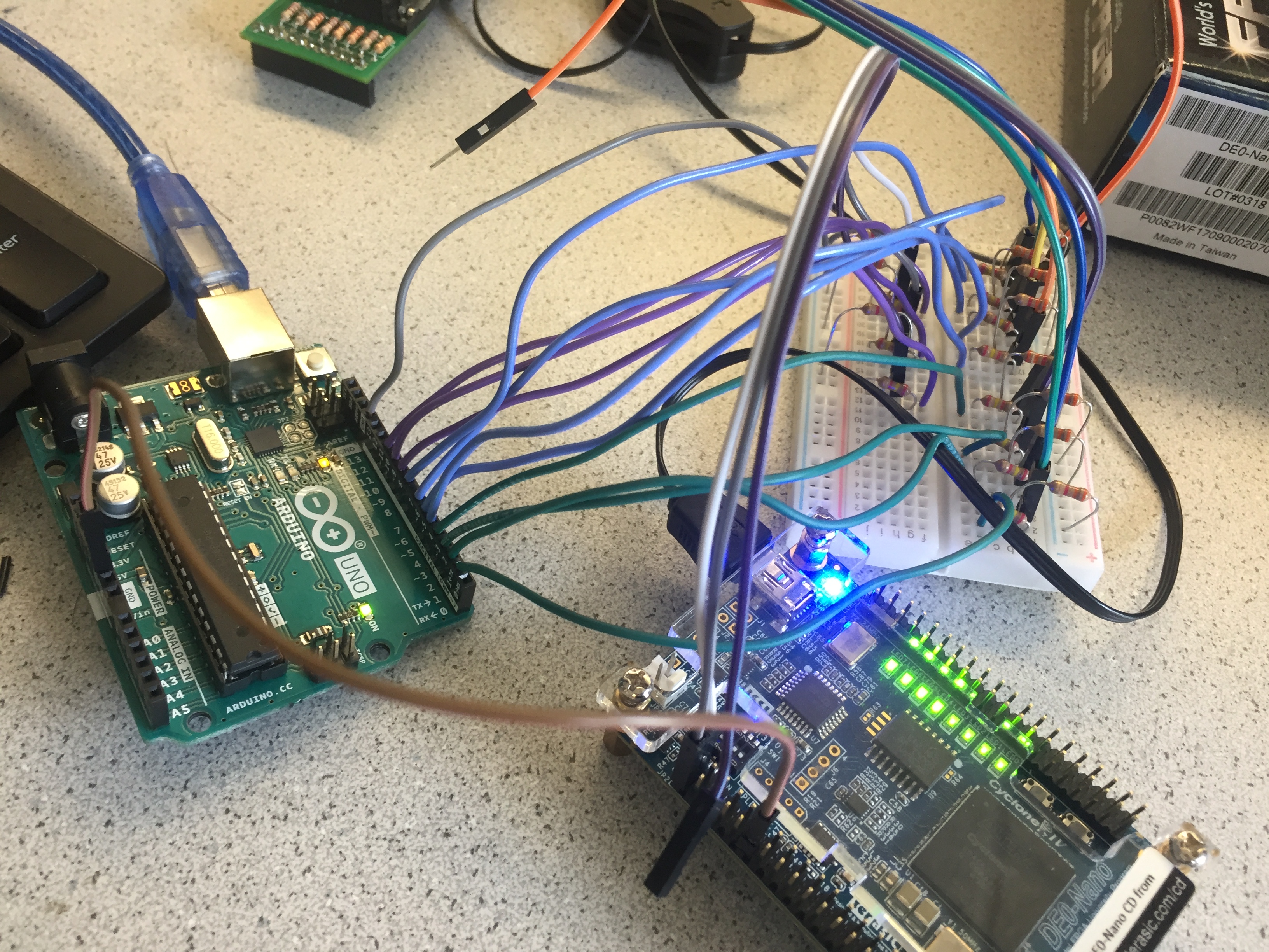
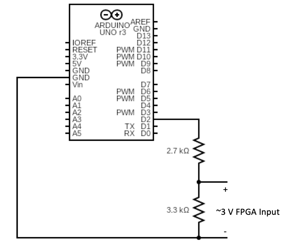
As you can see, there are A LOT of wires. We also had to put a voltage divider for every pin we were using on the FPGA, since the DE0-Nano operates at 3.3 V and the Arduino outputs 5 V on its digital pins. We used 2.7 and 3.3 kOhm resistors for the voltage divider, as we wanted to ensure that the output voltage was around 3 V so that we wouldn't accidentally fry an FPGA pin. We also made sure to connect the ground pins together. An example of one of the pins is showing in the diagram below.
The video below shows that our communication system worked. Here, we are driving one of the pins that are connected from the Arduino to the FPGA high and low, with a 3-second delay in between. You can see that when the Serial monitor prints "pin right high" the FPGA begins drawing the maze. When the Serial monitor prints "pin right low", the drawing process halts. We were able to do this by modifying the instrution RAM with our hypothetical maze, and we set the data from the Arduino as a write enable so that when the pin output is HIGH, the maze drawing resumes.