Lab/Milestone 4 - Radio Communication, Robot Detection, and Full Robot Integration
Objectives
In Lab 4, we finalized the interface between the Arduino and FPGA to update the display accurately using the maze data from the robot and fully integrated all components onto the robot, including the override button, finished mapping LED, microphone, and IR emitters.
In Milestone 4, we set up radio communication between the radio and base station, connected our Arduino and FPGA in the base station, and finalized our robot avoidance scheme.
Materials Used
- 1 DE0-Nano Development Board
- 2 Arduino Unos
- Various Resistors
- DAC Circuit board
- VGA cable
- A lot of wires
- 2 Radios (Nordic nRF24L01+ transceivers and breakout boards)
- 4 Infrared LEDs
- 1 Green LED
- 1 Phototransistor
- 1 Push Button
Procedure
Radio
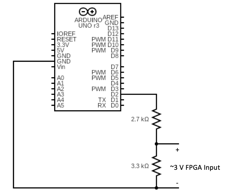
For the Radio, tested and adapted the radio code given to have the robot send maze information while navigating and have the base station draw to the screen using that data. To do this we had to encode the x, y, wall detection, and done signals into a 16 bit value with left shifts, and have the base station arduino decode that signal and set the correct output pins to high. Finally we had to wire up 12 voltage dividers (1 for each output pin) to convert the 5V output from the Arduino pins into 3V inputs for the FPGA pins. We decided to send all 12 bits of our maze data signal in parallel as it made for the easiest software side implementation. Several code snippits and images are below for demonstration.
Below is the function used to encode and send maze data from the robot:
      void sendIntersectData(int x, int y, bool leftWall, bool frontWall, bool rightWall) {
        radio.stopListening();
        senddata = 0;
        senddata += x << 7;
        senddata += y << 3;
        senddata += leftWall << 2;
        senddata += frontWall << 1;
        senddata += rightWall;
        radio.write( &senddata, sizeof(unsigned short int) );
        radio.startListening();
      }
Below is a small portion of the function used to decode data and set the appropriate Arduino pins:
      if(data & 1){ //right wall detected
        digitalWrite(A0, HIGH);
      }
      if(data & 2){ //front wall detected
        digitalWrite(A1, HIGH);
      }
      if(data & 4){ //left wall detected
        digitalWrite(A2, HIGH);
      }
      if(data & 2048) { //other robot detetcted
        digitalWrite(7, HIGH);
      }
Below is a circuit diagram of the voltage divider used to connect the Arduino and FPGA pins:
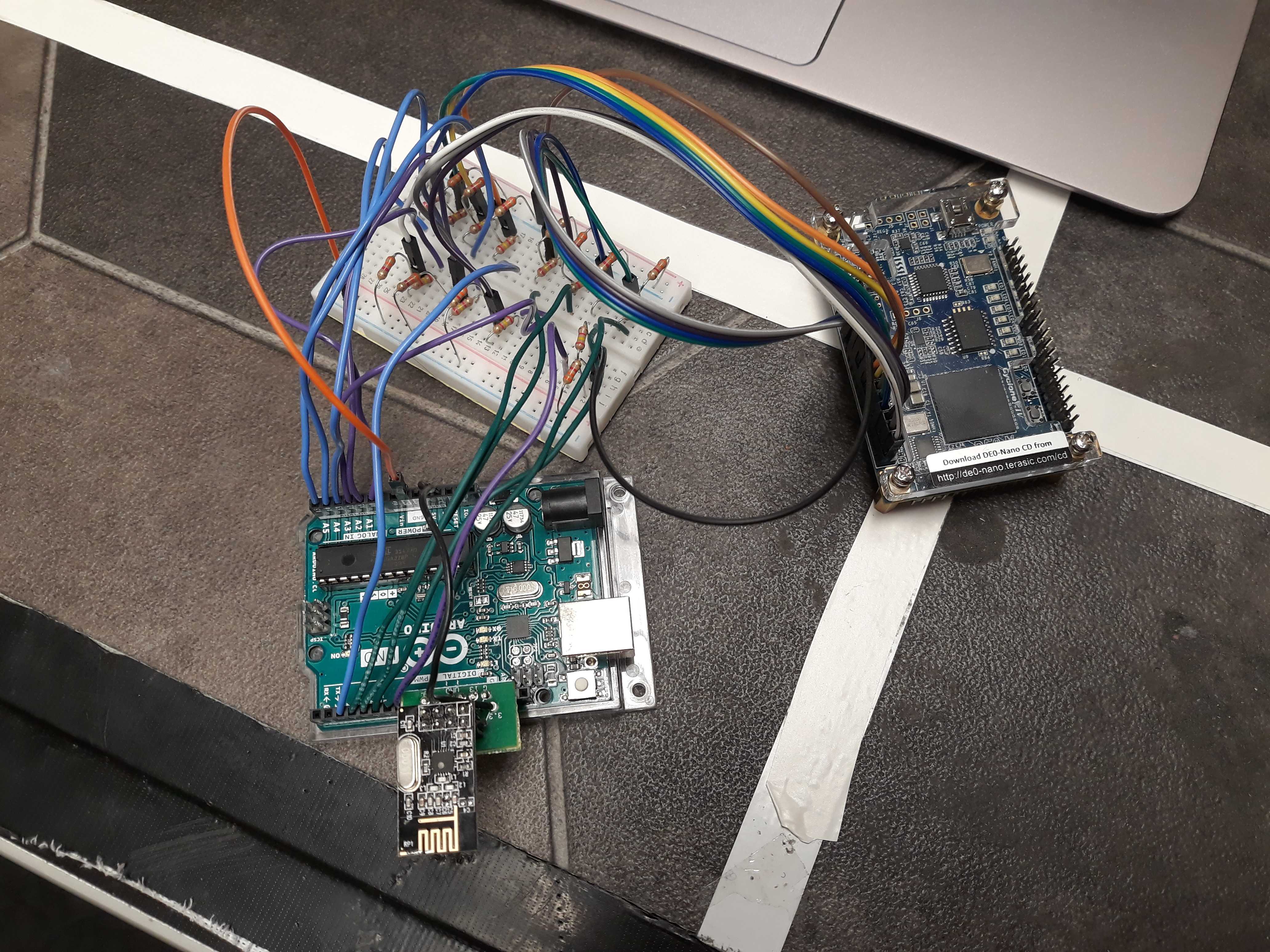
Below is a picture of the base station wiring with 12 of the above voltage dividers(note how both analog and digital pins are used for output from the Arduino):
- A linear array which stores coordinates of seen points,
- A linear array which stores back-pointers to seen points, whose entries line up with the previous array,
- A two-dimensional Boolean array which tracks which points of the maze have been visited,
- An integer that tracks the last valid entry in the linear arrays,
FPGA
For updating the FPGA display, we have added drawing the robot navigating through the maze. We follow a similar procedure as drawing the mazes as shown in Lab 3 using counters to draw the different pixels on each clock cycle. We have also implemented a RESET button to our FPGA code, which resets the stored memory to all 0s and the maze drawing logic to its initial state. This allows for restarting all the maze navigation without having to power loop the FPGA of the Arduinos. This was done by adding the input RESET to all the always blocks and resetting values to the initial values when RESET is set to 1. For indicating when the maze has been drawn correctly, the display is updated such that the color of the robot and the background are flipped to indicate the maze drawing has finished. This is indicated by the robot once it has finished navigating back to the initial position.
Below is a video of our robot mapping a short maze with the FPGA updated as it goes. Note how the display changes when the robot is done.
Data Scheme to store maze data
For storing maze data for the purposes of DFS, we store the following information:
We can know whether we have finished navigating the maze by iterating through the seen list from the last valid index to the first entry and checking each point for whether we have visited that point in the maze. By storing one back-pointer for each point, we can avoid having to store all of the wall information for each point and instead know one way to walk backwards through the maze.
Radio communication with DFS
For sending radio information during DFS, we send position information of the robot to the base station every time the robot reaches a new intersection. This includes when we have to avoid a robot and go backwards a point in order to have the robot move out of the way and while backtracking through the maze. However, in these situations we decide to not send wall information together with the position in order to avoid sending incorrect information to the base station. Basically, we only send wall information the first time we visit a given point, with the exception of the initial starting position. We only draw the back wall of the starting position once we return to the initial position after DFS has finished executing. Below is a snapshot of our robot being able to transmit information to the base station. It also has audio detection.
Robot Detection
For avoiding other robots, we act differently based on whether we detect the robot while we are line following or when we are at an intersection. For the case that we are line following and we detect a robot, we perform a 180° turn and return to the previous intersection, then attempt again to travel to our destination. If instead we only detect the robot while we are at an intersection, we wait for a short period of time to see if the robot gets out of the way quickly. If the robot gets out of the way, we continue as normal, otherwise we backtrack one point and attempt to return to the point we were at before and then go to the original destination.
Full Robot Integration
This portion of the lab consisted mostly of soldering wires together and ziptying parts down as we put the microphone(+ filter circuit), radio, and phototransistor on our robot. We also had to add a push button to the protoboard and connect that to a digital input pin of our Arduino; this would be the override button to tell the robot to start navigating in case it fails to start when hearing the 950 Hz tone. Beyond that we had to add 4 IR leds connected to the power and ground rails (with a 300 ohm series resistance) of our protoboard and hold them down using zip ties to stay horizontal at 5 inches above the ground so that other robots could detect ours. Finally was the issue of powering our microphone circuit; when we first tried to power it using the protoboard, it created too much noise making the output unreadable. We ultimately set up a voltage divider with 5.6k and 4.6k ohm resistors with a 9V battery to give the microphone the 5V it needed.
Below is a video of our robot navigating a maze and turning on a green light once it's done mapping. Note that the robot only starts mapping out the maze after the override button is pressed:
FFT
Our original FFT circuit can be found in the Lab 2 page. Everything worked then, and then we didn't touch it for weeks following because we didn't have to use it for any of the labs and milestones. However, while integrating the full robot, we quickly realized that our FFT circuit stopped working. Below is a video of our old circuit that we tested the week before circuit. This is without the microphone and with a function generator, and even without the microphone it didn't work properly.
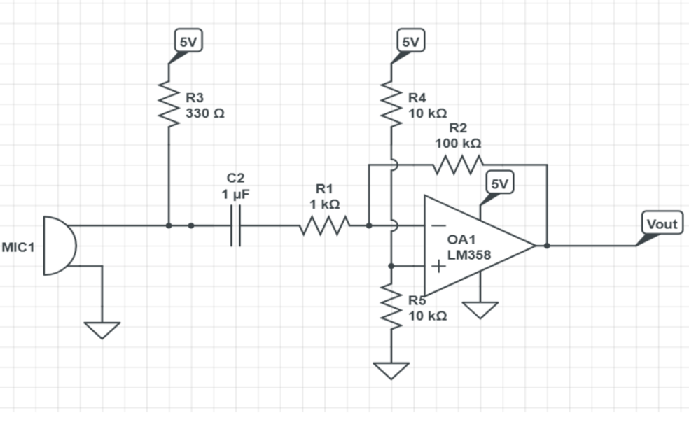
You can see that there isn't a clear distinction of which bin to look at. Also, the output of this circuit was not at all what we had experienced in Lab 2. We decided to build a new circuit because we couldn't figure out what was wrong with our original circuit. We swapped out every component, soldered onto a protoboard, and tried to vary the gain of the op-amp, all to realize that the circuit still didn't work as intended. Because our circuit was very complex, we decided to simplify it and go with an active band-pass filter.
Below is our video of the robot moving with the new circuit when it detects the 950 Hz tone in the test melody.
One issue we had was that because we originally only checked for magnitudes of the bins, we didn't account for the relative amplitudes. This means that if a tone with any frequency was played loud enough, the robot would register that as a 950 Hz tone. So on the day of the competiton we decided to look at ratios of the magnitudes of different bins. This worked out really well, because our robot actually detected the tone on competition day! (Before it got ran over by another robot)