Go To:
Home Page
Milestone 3
Milestone 2
Goals:
- Detect the different treasures at the three classified frequencies: 7KHz, 12Hz, and 17Hz
- Autonomously detect walls using IR sensors
Detecting different treasures:
First, we obtained three treasures and verified, using an oscilloscope, that these treasures were generating the desired frequencies as listed for Milestone 2: 7KHz (bin 47), 12KHz (bin 80), and 17KHz (bin 114).
Next, we had to generate code that would light up a different LED for each frequency. As seen in the code below, each if/else if statement checks for a spike in the FFT for the specific bins listed above. The peakAt() function, described in more detail below, is essentially a threshold that checks 5 bins to see if the treasure is within the 5 bins of each treasure. If a specific bin is a match, then the corresponding LED would light up.
   if (peakAt(46)) {
      digitalWrite(3, HIGH);
      }
    else if (max(fft_log_out[82], fft_log_out[83]) >= 50) {
      digitalWrite(7, HIGH);
    }
    else if (peakAt(113)) {
      digitalWrite(5, HIGH);
    }
   else{
   digitalWrite(3, LOW);
   digitalWrite(7, LOW);
   digitalWrite(5, LOW);
    }
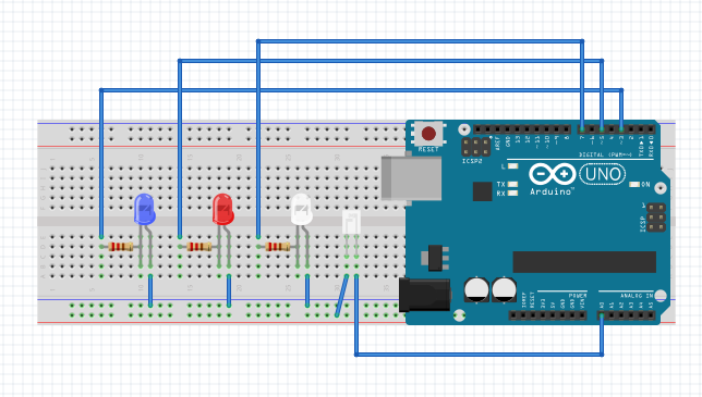
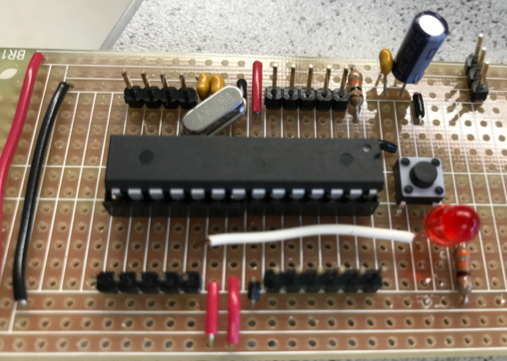
Circuit:
When the phototransistor, as seen to the right of the three LEDs, senses a 7KHz frequency, the white LED turns on. When the phototransistor senses a 12KHz frequency, the red LED turns on. When the phototransistor senses a 17KHz frequency, the blue LED turns on.
Testing and debugging:
When we first tested our code and circuit, none of the LED’s would light up. The wiring of the circuit looked correct as well as the logic to our code. Then we realized that we used fft_input[] instead of fft_log_out[] in the following section of the code:
boolean peakAt(int binNumber){
  for(int i = binNumber; i< binNumber +5; binNumber++){
    if (fft_log_out[i] >= 50){
      return true;
    }
  }
  return false;
}
Changing this fixed our problems and allowed us to accurately detect the different frequencies.
The function peakAt() as seen above checks to see if there is a peak around a certain bin by testing
a range of 5 bins around the expected bin. The function returns true if any of the 5 bins has an amplitude
greater or equal to 50.
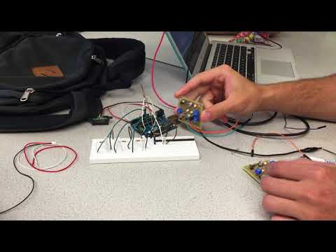
Results: Here is a video demonstrating our abiity to detect different treasures:
Detecting Walls:
We have both long and short range IR sensors at our availability.
Datasheet for short-range IR sensor:
http://www.sharp-world.com/products/device/lineup/data/pdf/datasheet/gp2y0a41sk_e.pdf
Datasheet for long-range IR sensor: https://www.sparkfun.com/datasheets/Sensors/Infrared/gp2y0a02yk_e.pdf
Important points from short-range datasheets: Both have a supply voltage of 4.5-5.5 V Both have a max analog output voltage ~3.1V Short-range easily detects distance around 3-5 cm Long-range easily detects distance around 10-30 cm Both output approximately the same voltage for very short distances and very long distances
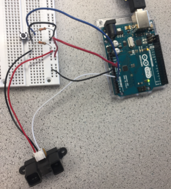
We first decided to experimentally characterize the sensors with the Arduino. We first connected the short range IR sensor to the Arduino 5V supply and GND (with 330 Ohm resistor) and tested the output with a multimeter to see if we were getting an output voltage.
We then connected output of the sensor to the arduino and used the serial monitor to print the output.
We implemented a pushbutton so that the monitor would only print when the button was pressed.
We then collectected the output of the sensor across from a wooden block at various distances from the sensor with the following results:
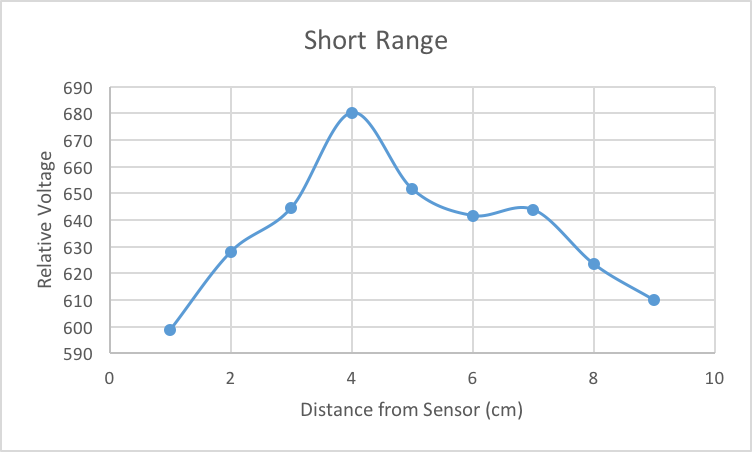
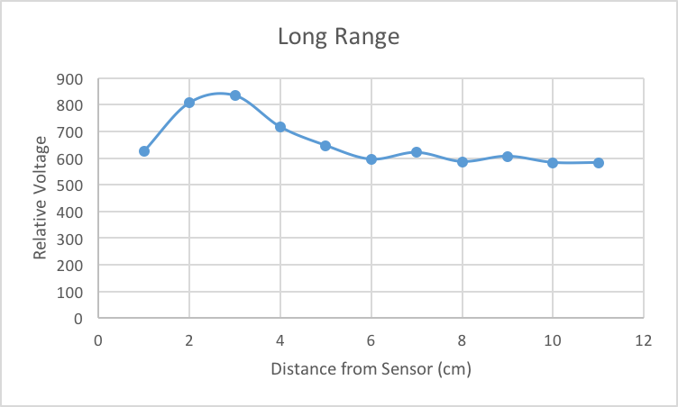
The length of the square is approximately 30 cm, so we want to be able to detect a wall that is around that distance away. Consequently, we chose to use the long-range IR sensor.
We then mounted the long-range IR sensor on the robot, and hooked up with power rail, ground, and analog pin A0 for analog output.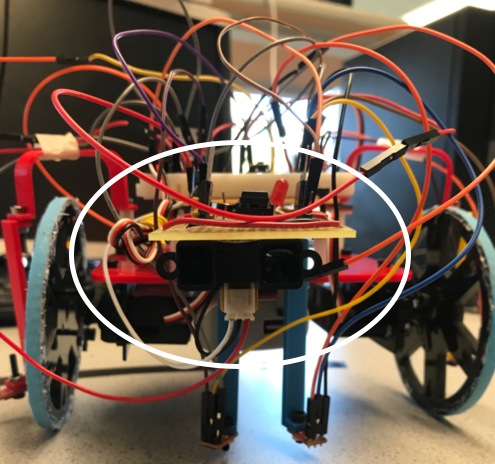
We also incorporated the following code that enables the robot to stop and turn its LED on when there is a wall roughly 30 ~ 35cm in front of it.
We played around with the threshold voltage reading. The output does not vary much within 0 ~ 25cm from 600 (/1023), but make a siginificant drop above 30cm. Because we want it to detect the wall at roughly 30cm away, we chose the output value at this distance, which turned out to be 300. One thing to be careful is the evenness of sensor position. We decided to attach the sensor with a tape until we come up with a finalized design of the robot. Due to its weak bonding, the sensor tilted forward, in which case the sensor output value changed unpredictably.
float ans = analogRead(An_PIN);
while (ans > wallThreshold){ // wallThreshold = 300
  rightMotor.write(90);
  leftMotor.write(90);
  digitalWrite(13,HIGH);
  ans= analogRead(An_PIN);
}
For the actual implementation of wall detection, the robot will not stop when a wall is detected. The robot will instead “remember” that there is a wall beyond the intersection, and it will turn either left or right at the intersection.
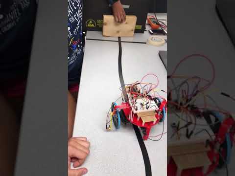
Results: Here is a video demonstrating our abiity to detect walls:
Transitioning to using 2 Arduinos:
While this was not a part of the milestone, we started to consider that there are not enough input analog pins for all the sensors the robot needs. We debated ideas of how to add more analog inputs to the device, since we need 11 (1 microphone, 4 line sensors, 3 wall sensors, and 3 treasure detectors, 1 pushbutton) and came up with the following ideas:
Use a mux Get Arduino affiliated extension of pins Use another Arduino chip, which control different main sensors
Our current plan is the last one. We are already working on building our own board with the ATMega chip from the Arduino soldered onto a perfboard, so it would not take up too much extra space to add another microcontroller chip. Also, functions such as the fft are very memory heavy, so it may be more efficient to have a separate microcontroller responsible for this task.
Arduino1
Analog input: 4 line sensors, 2 wall sensors
Digital input: Wall detection from Arduino2, Go signal from Arduino2
Digital output: 2 servos
Uses: 6 analog, 4 digital pins
Arduino2
Analog input: 1 microphone (A3), 3 treasure sensors (A0, A1, A2), 1 wall sensor (A4)
Digital input: 1 pushbutton (D1)
Digital output: Wall detection (to Arduino1) (D2), Go signal (D3)
Uses: 5 analog, 3 digital pins
Go To:
Home Page
Milestone 3