jks253
Features
Lab 3 Goal
The goal of Lab 3 was to give Jerry an ear. The Frankenstein is slowly coming to life. Note that the optical circuits were also completed during this time.
Lab notes
A small microphone circuit was wired in, the output thereof being passed through an amplifier circuit, and then through a high-pass frequency circuit, before being fed into one of Jerry's input pins.
The circuit was, at each step along the construction, tested in various ways.
By the end of the lab, Jerry was able to accurately detect paritcular one-tone signal frequencies, enabling us to deliver commands to Jerry via sound.
Problems and resolution
Several problems arose along the way, most notably the circuit construction itself.
Several parts had to be replaced from the initial iteration of the circuit, and much troubleshooting had to be done so as to determine which part(s) of the circuit were improperly constructed.
Graphs and Simulations
Matlab was used to simulate what the output of a signal-frequency-sweep going through the circuit and Jerry would look like:
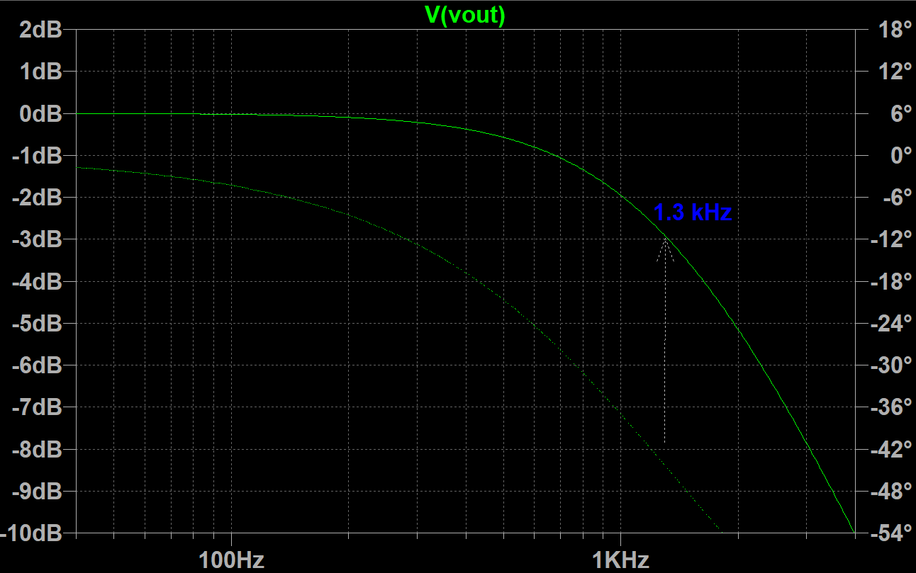
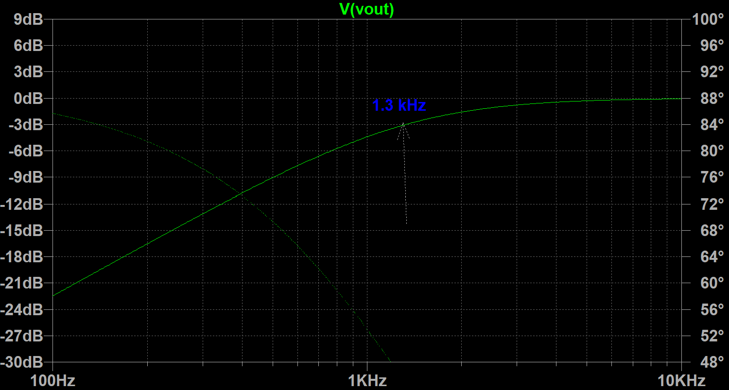
Shown above are, respectively, a low-pass and a high-pass filter, each marked with their cutoff frequencies.
When the experiment was run, similar results were achieved.
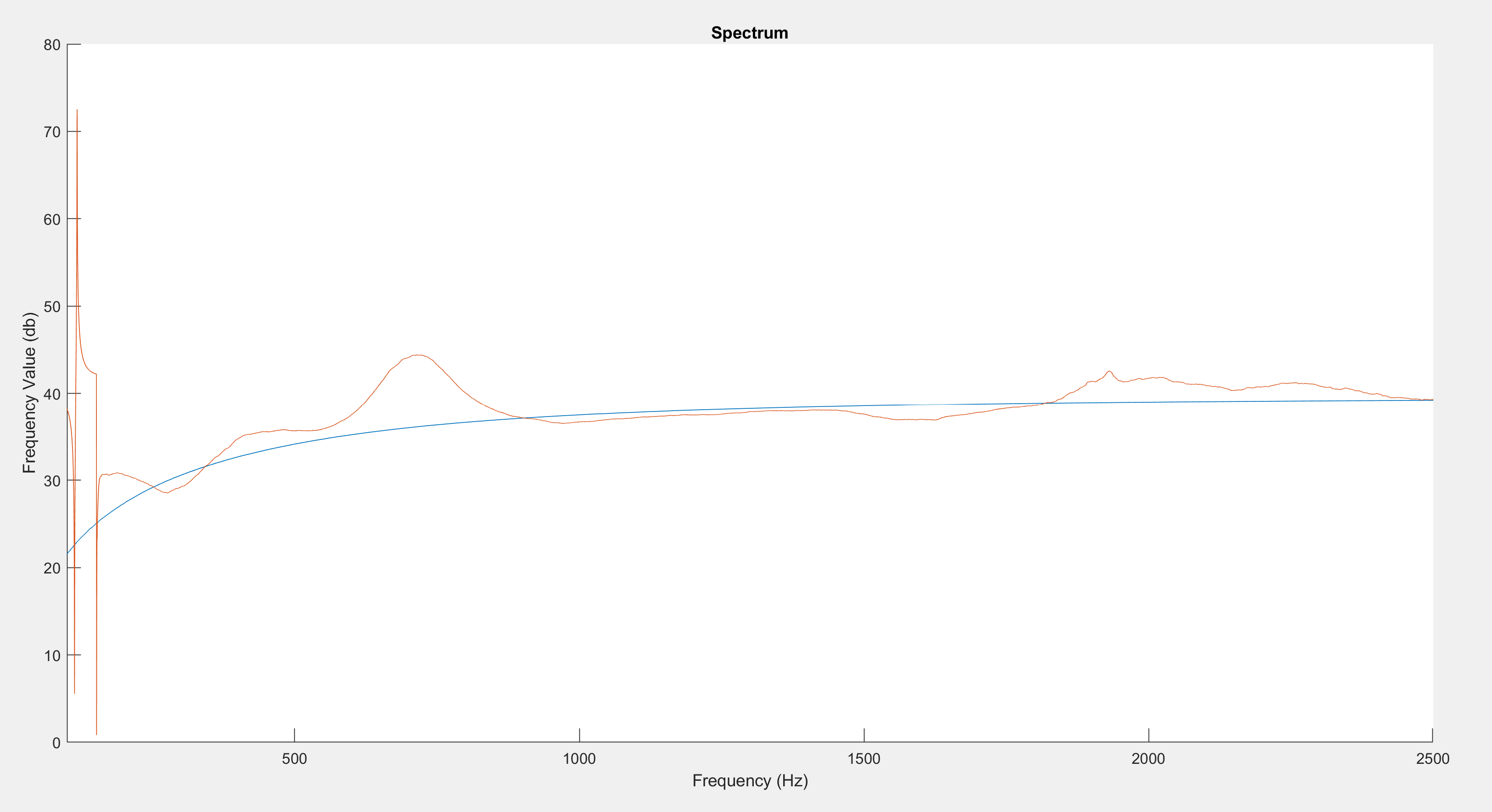
Observe how neatly the two graphs superimpose onto one another.
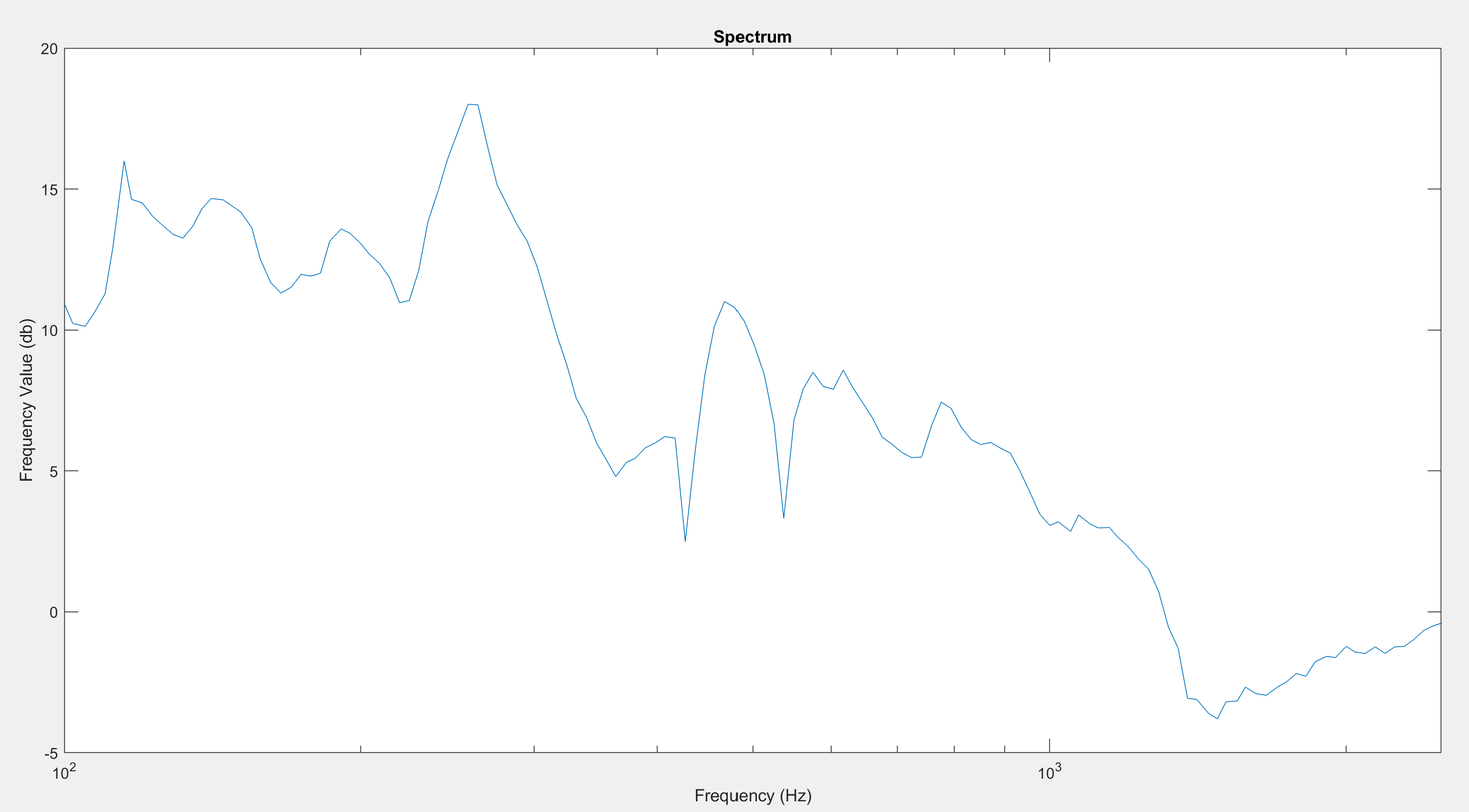
Pictured here is the difference between the superimposition.
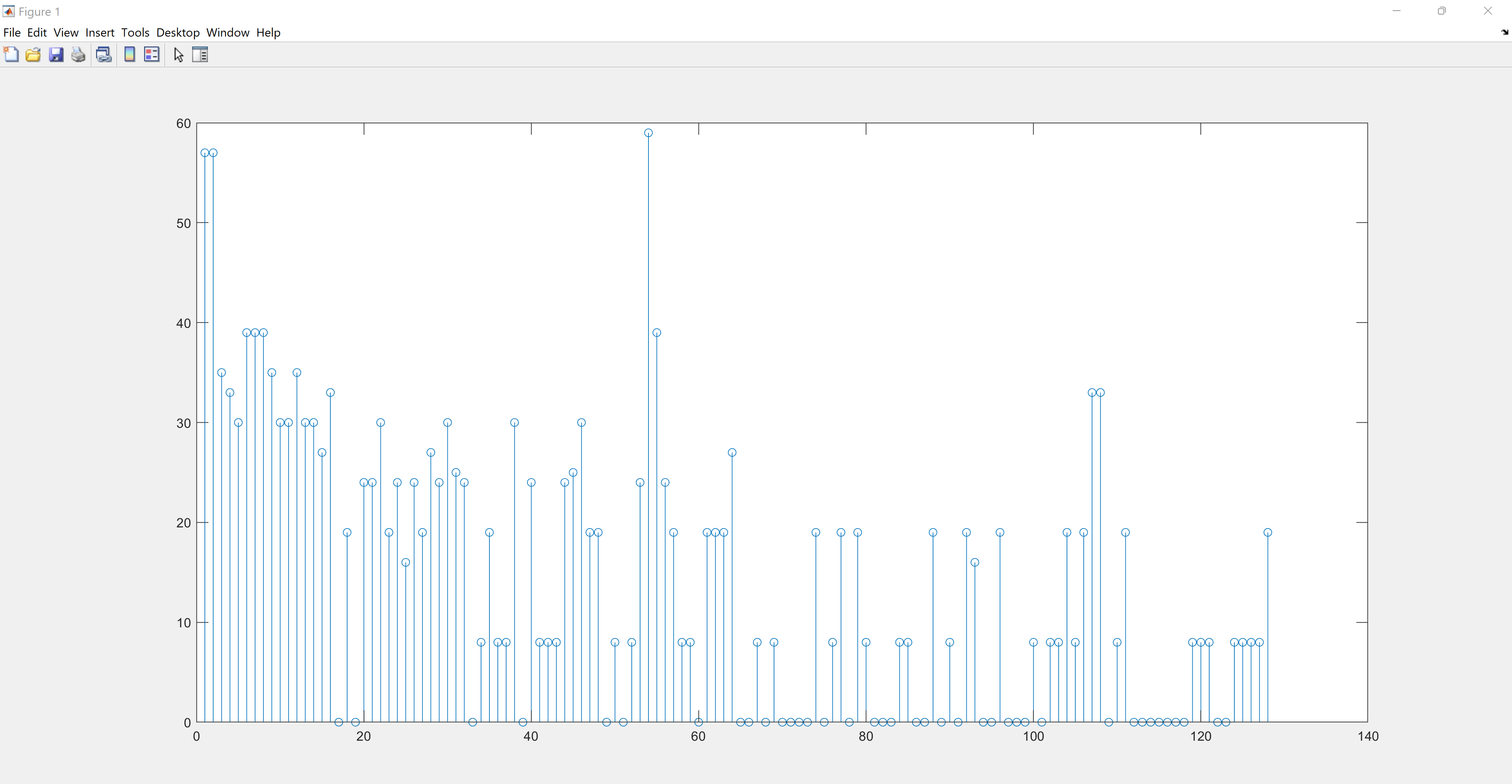
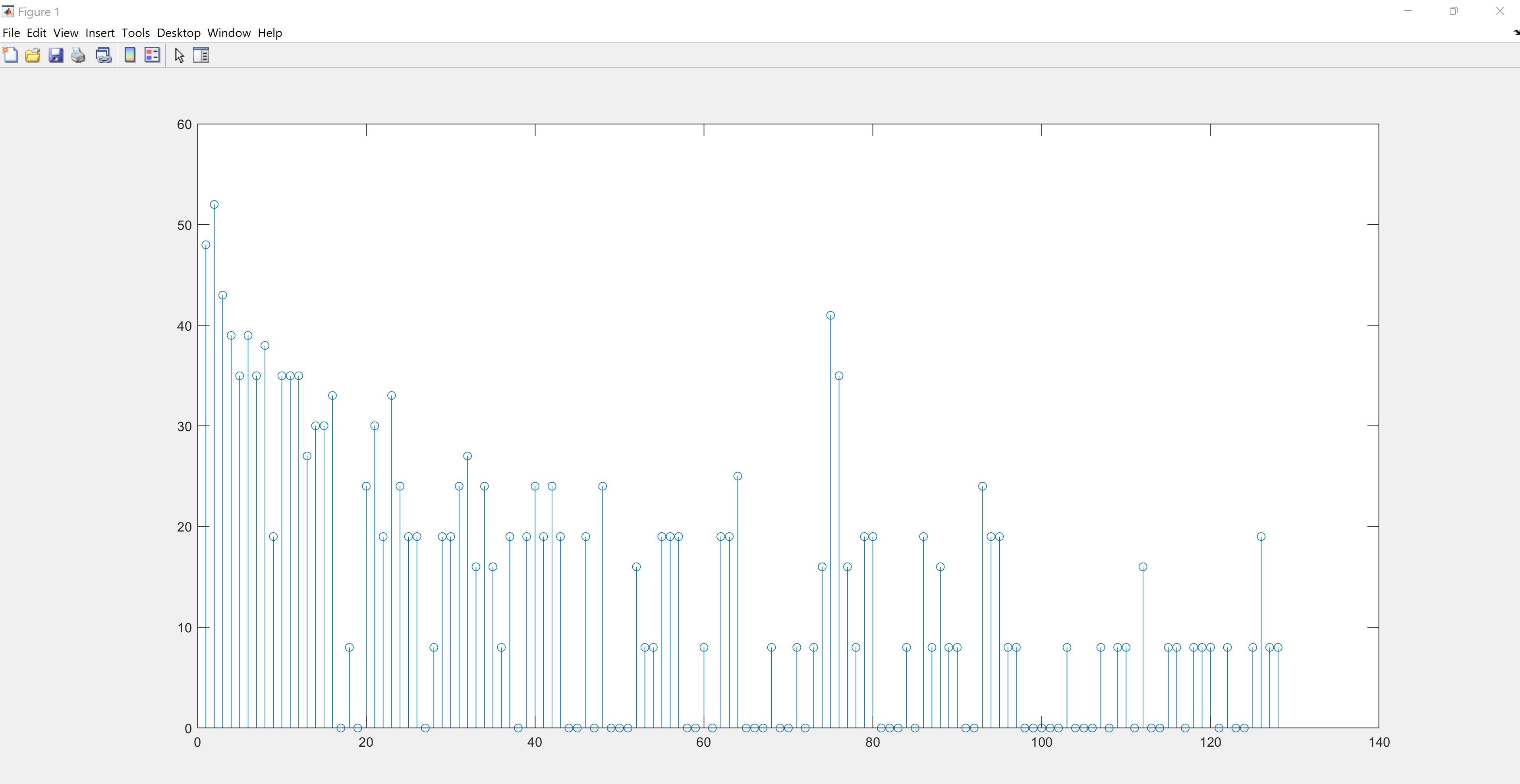
Pictured below is the difference achieved by running the output of the speaker system through the amplifier circuit. The first picture is without the amplifier, the second is with. Notice the jump from a 5k amplitude to an 8k amplitude.
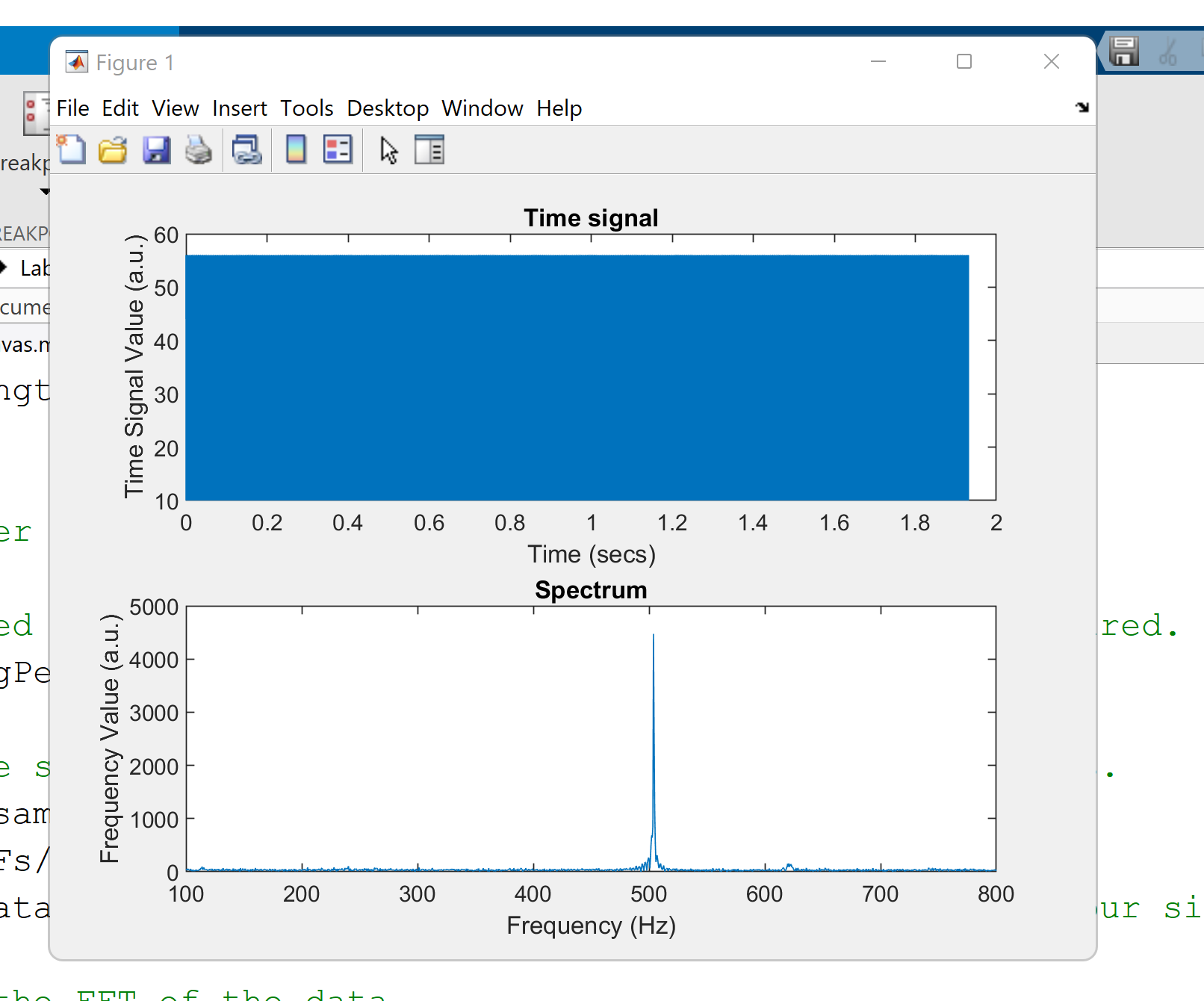
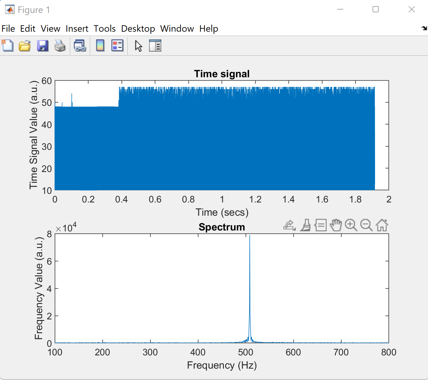
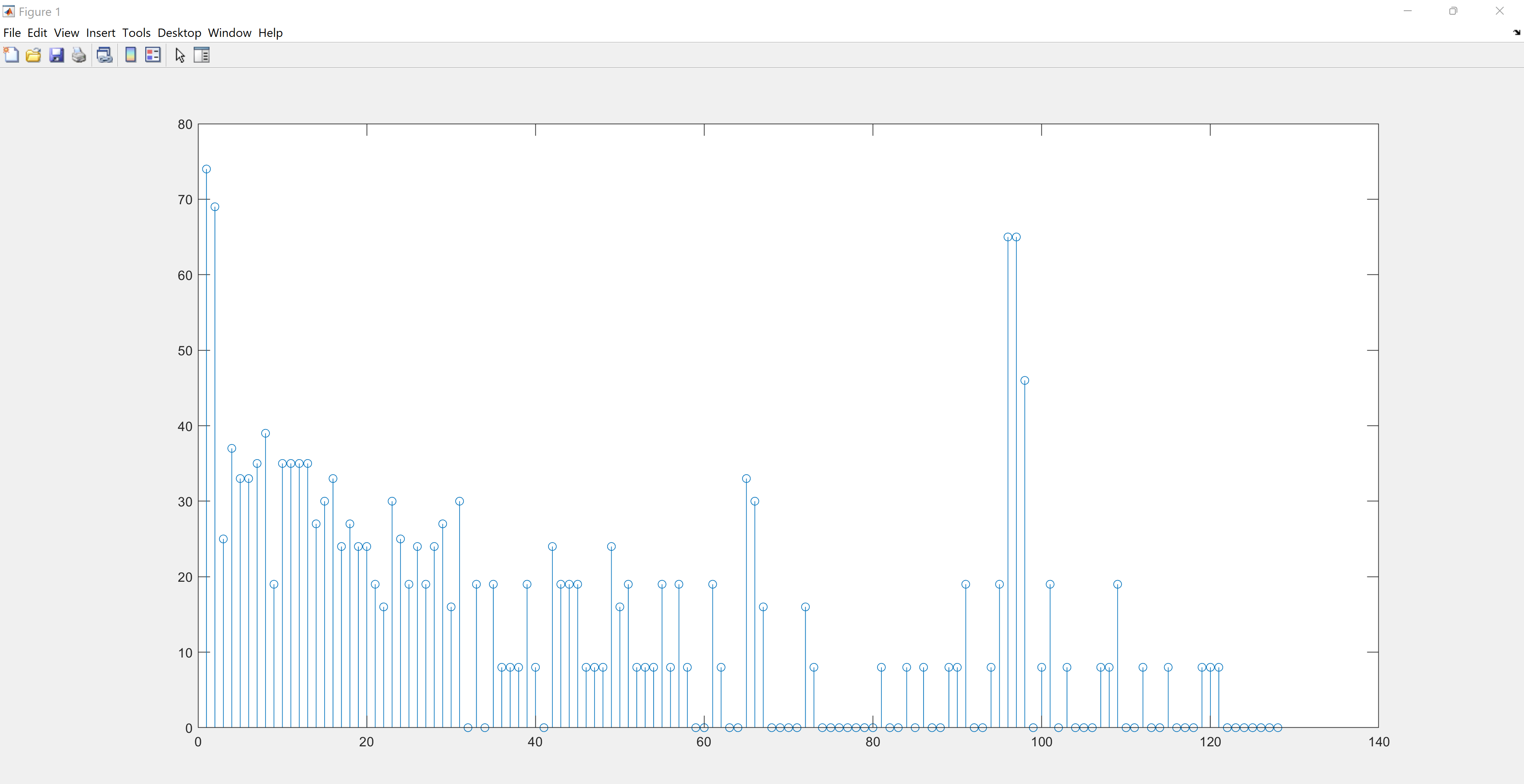
As shown below, Jerry is clearly capable of identifying which frequency is being played for 500, 700, and 900 Hz tones.