Go To:
Home Page
Milestone 2
Milestone 1: Line Follower!
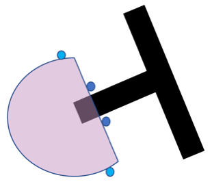
Hardware
Main Chassis
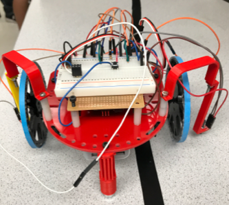
The size of the main plate was not big enough to accommodate all of them without protruding out to sides.
The stability and robustness of the line-following robot largely depend on how symmetric the overall chassis is.
Therefore, we decided that we will use the free space available on the rear sides of each component.
The battery is attached to the rear side of the main plate facing the floor, between the two servos.
Then on the opposite side, we mounted a perfboard using four small columns that are screwed on each corner.
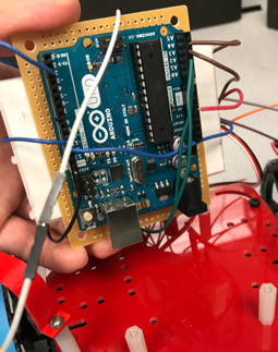
This gives enough space for the Arduino Uno to be attached to the rear side of the perfboard.
Lastly, the breadboard is attached and placed on the perfboard facing the ceiling.
In essence, the vertical placement of three major heavy components should contribute towards maintaining the symmetry and balance of the robot.
Circuit
There is no huge change from our initial design for circuitry (Detailed design available in the Laboratory 1 section). The only change is the addition of QRE 1113 line sensors. Each need to be powered, grounded, and connected to Arduino’s analog pins.
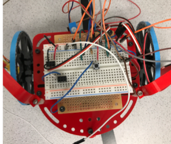
Line sensors
We use four QRE 1113 line sensors. The front two sensors, located close to each other, maintains the robot on the straight line.
The rear two sensors, located next to two respective wheels, detect the intersection, at which they override the other two sensors and make the robot turns 90 degrees.
Future Improvements
-
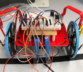
Although our vertical line of placement gives us the benefit of symmetry, the circuitry becomes very messy with lots of electric wires mixed haphazardly.
In addition, troubleshooting is more difficult, because we have to flip the breadboard to see the Arduino,
and in the process, wire connections are vulnerable.
In tackling this problem, we are building Arduino on the perfboard, so that we can integrate Arduino and the breadboard, simplifying the circuit design and decreasing the number of wires. -
The robot turned out to be not as symmetric as we hoped.
Even though the servos were calibrated well, when the robot moves on a plain surface without any black line, it tends to tilt to one side. We believe this is due to the wheels not perfectly aligned to the main body.
This imbalance translates to the jerking motions. Even though the line is fairly straight, the robot continues to hit the line, and it has to adjusts its path unnecessarily. -
The sensors need to be closer to the surface.
Because a set of three pins is soldered into the sensor’s Vcc, Output, Ground, when the sensor is mounted to the robot, it is not perfectly parallel to the surface. Thus, the farther the sensors are away from the floor, the more likely it is that they pick up signals from the black line.
As a result of these improvements, we believe that the speed can be maximized, and the line-following motion becomes more robust!
Software
Following the Line:
To begin we created a simple circuit with the infrared sensor to figure out what range of values we would be dealing with. We found that depending on the environment, the values between the black tape line and off the line changed. This means we couldn’t use any hard code values.
Next we decided on the placement of our sensors. Originally, we had them both on the line and would correct when one of them left the line but after multiple trial runs we decided that the sensors on either side of the line was a better choice.
 _//LINE FOLLOWING <br>
  rightMotor.write(forwardR);  <br>
  leftMotor.write(forwardL);  <br>
  if((rightLine - leftLine) > 10){ //right sensor hit line <br>
     rightMotor.write(forwardR + 3);  <br>
    } <br>
  else if ((leftLine - rightLine) > 10) { //left sensor hit line <br>
    leftMotor.write(forwardL - 3);<br>
  } <br>
}_
As seen above, every loop in the code we compare the values of the left sensor and the right. If their values are roughly the same then we know they are both not on the line and we can continue moving straight. We found that a difference of 10 between them was enough to confidently say one of them must be on the line. If one of the sensors hit the line, our robot would turn that way to make sure it continues following the line. We did this by slowing down one wheel to allow the robot to turn a slight amount.
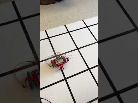
Here is a video of our robot following a line:
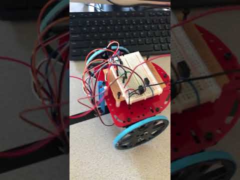
Figure Eight:
In order to get our robot to be able to turn we had to add sensors to detect an interesection. We decided to add these on the outside of our wheels, roughly in the middle of the robot’s body.
Once the intersection sensors were hooked up, we had to decide how to utilize them.
We were faced with an issue was we originally tried to use a hardcoded value for the intersection sensors. This turned problematic as the sensors would sometimes randomly think it saw a line and turn.
Here is a FAILED attempt of our robot:
Our current design compares the last value of the sensor to the current value. If there is a big jump from one to the other then we know the intersection sensors have hit a line and thus the robot must be at an intersection.
After finding an intersection our robot has to turn. We originally decided that we should turn until one of our front line sensors hit the line because then we knew that it had turned the 90 degrees. After trying to implement that multiple different ways we found that it would just be easier to have the robot’s wheels spinning max speed in opposite directions for a specific amount of time.
Here we ran into an issue of our robot being stuck randomly turning and never actually moving after the turn. We realized that after we turned the intersection sensors were triggering another turn because it was registering the perpendicular line we just turned off of as another intersection. This was an easy fix as we just had the robot drive straight for .4 s so that it could clear the intersection and the line following could resume until the next intersection.
The last part of completing the figure eight was getting the turns down. We created a boolean that kept track of if the robot was supposed to turn left and every four turns it toggled giving us the figure eight.
  if(checkInt()){ //if its at an intersection
     if(turnL){
       turnLeftInt();
     }
     else{
       turnRightInt();
     }
     turns++;
    if(turns%4 == 0){
     turnL = !turnL;
    }
  }
Here is a video of our robot completing a figure eight:
 .
.
Go To:
Home Page
Milestone 2